 |
page about
calibrating the track zero
|
 |
| |
I really donīt want to disencourage anybody, but the task of
recalibrating the track zero is really tricky, it requests some
experience and its
only possible to execute the task with special software and special disks
- and its also strongly recommended that the user is able to
handle
( with at least basic knowledge of ) and work with an osciloscope. there
are different kinds of attempt to the task depending to the
availiable
items. If one of the listed items is missing it still might be possible
to solve the task - but it becomes more complicated requests
more time
and more advanced experience to overcome such a handicap.
I will explain the different possible tasks again in the order sorted by
difficulty from simple to more difficult and finaly i will
explain the
"mission impossible" ( thats an attempt with missing tools and "try and
error" method to get at least a drive able to read and write but
but not with accurate calibration but rather more to say a "somehow
acceptable result" ).
|
|
| |
First of all again weīll start with the basics - so lets examine how the
Apple works normal, when it starts accessing a disk and what
part
of the game the track zero plays in that game and what happens if the
track zero is not recognized by the system.

|
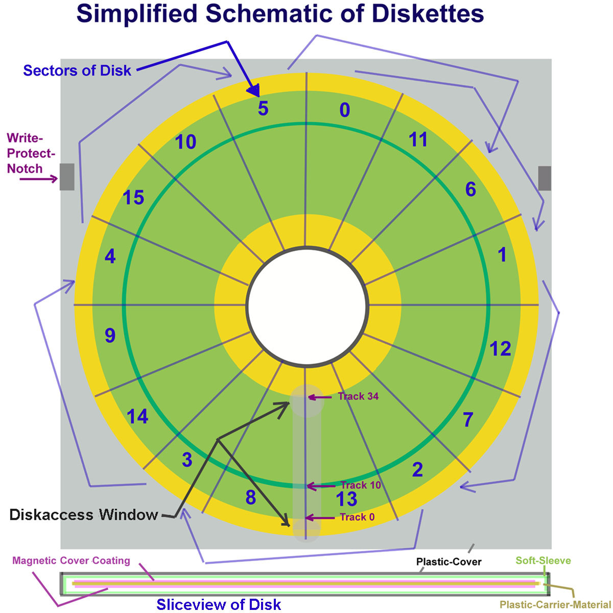
Any kind of access to the disk performs the following
steps:
1. recalibrate diskdrive ( thats the knocking noise when
the read/write-head is pulled back to the outside of
the disk and after the read/write-head sled hits with
the positioning-limiter some times the positioning
stepper motor and then moves the sled one step
ahead towards the center and assumes this to be the
track zero )
2. the controller tries to read this track and expects
this track to contain the information determined to
be at track zero ( this information track should
contain the FAT and the information of the diskformat
( i.e. dependent to the operationsystem - how many
tracks, the amount of sectors per track, the track
where additional parts of the FAT is allocated and
further information * )
remark: FAT = File Allocation Table
* = further more detailed information at
the end of this page !
The information in this track zero is normally written
first time to the disk when disk becomes formatted or
initialized by the INIT-command. Thereafter this track
becomes updated, if the contents of the disk is
modified (i.e. update amount of free sectors ).
3. Then the read/write-head-sled is moved ahead
towards the inner part of the disk to the desired
track and sector to start reading or writing to the
disk. |
 |
4. In case of booting from disk its the same procedure
and the steps from 1 to 3 are repeated step after step
to get the data from the FAT,
reading the sectors where
DOS is stored sector by sector untill DOS is loaded
completely to memory, then the computer performs the
instructions of DOS
itself - i.e. it looks for the program that was left as
initial startup program in DOS - mostly common the
"hello"
program in DOS or the
SYS-file in proDOS.
*) this explenation is at the very end of the page !
If one of the steps above fails the computer or DOS
will display an errormessage ..... If the track zero
isnīt found - the ROM F8 with the
autostart routine will display the message "no System"
or similar - if the mistake occurs later i.e. a part of
DOS was not loaded the
system will display a message like "read error" and if
the mistake happens more later i.e. DOS loaded but
"hello" not loaded due to
malfunction the message will be something like "read
error" or "missing file" or "file not found". In some
occasions DOS simply crashes
to the monitor-prompt.... this is for example a common
kind of proDOS to crash.... with some experience and
advanced knowledge you
might be able to determine where the crash occured by
the adress displayed at the monitor prompt..... - but
thats another story....
Before we start talking about the
hardware here some things to remember / keep in mind:
Of couse before taking next steps a cleaning and
speedadjustment should be performed just to make sure
that none of the other mistakes
cause errors and making proof of the fact that the drive will
be useable after readjustung the track zero... ( - at
least, if you have another
drive to boot from ).
Allthough a drive might be misaligned - it still might be
used.... the trouble is just that
it canīt read disks from other systems and that disks
written with this disk canīt be recognized or read by other
drives ( so at least this should be detected
before starting to attempt the
hardware..... - if a second drive is
availiable that is aligned proper you should set that
drive to be first drive and move the misaligned drive to
the second place to checkout some basic functions: does the drive
pass the task of formatting or INITīializing a
disk and can the drive read
back data that has been written to this disk by itself (
i.e. not from another drive written ) ?
Does it pass for example a
speedtest and certify
correct speed ? If it does and if the first drive can read
write disks that can be exchanged with other drives
because it is aligned correct, do
you exchange disks containing data with other systems ? If not -
you could for example dicide to use the other misaligned
drive exclusive
for own data and abuse that drive as a kind
of encryptic security system, being sure nobody can
access your private data .....
Disks could be marked with special sign on label to indicate with
which drive they may be used....
Bear also in mind if you are using ADT this
whole trouble might not bother you, if the disks you use
are generated and used only by this
drive... the trouble of
misalignment only affects to you, when there is somehow
a use with other drives too.....
If you have judged this facts and dicide to proceed and go ahead to
align the track zero, then go ahead with this page... |
|
|
| |
So now after this basic explenation lets get to the
hardwarepart with pictures and connect that with the explenation
above......
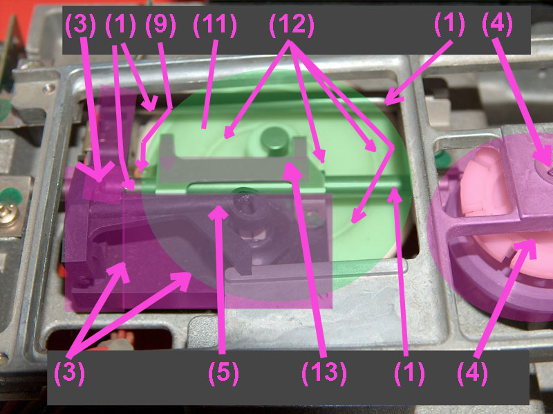
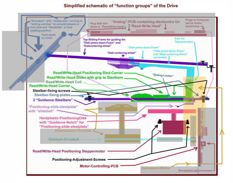
First of all looking to the picture
at the right side -
those parts that are not within the game of alignment
have been cóvered with gray.
If you canīt read or remember the comment just switch
back to
the picture at page
1 to read within the large picture.
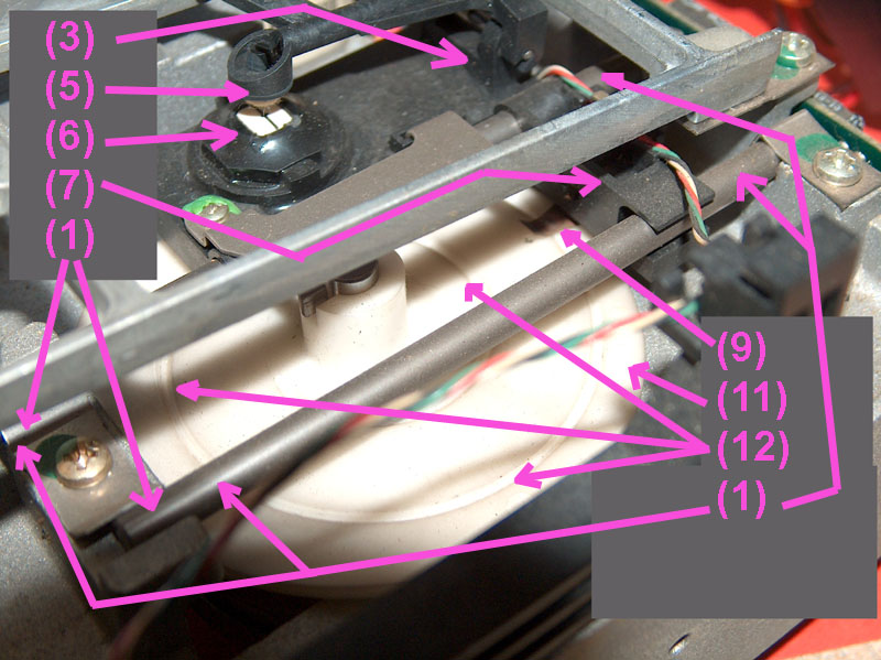
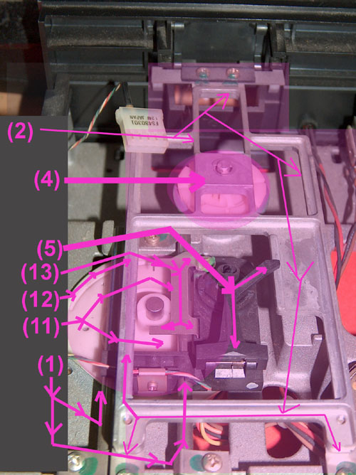
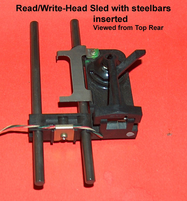
For this task only three groups become important:
the fixed group of the 2 steelbars
(1) and the
topframe (2 )
that guide the sled.
the sled itself (3 ),
that carries the movable parts of
the drive ( on top: diskcenteringwheel
(4) , and the
lever with the disk-pressdown-foam
(5) - on the
bottom: the read/write-head
(6) , the sledcarrier
(7)
with the guidance notches
(8) running along the
steelbars (1),
and
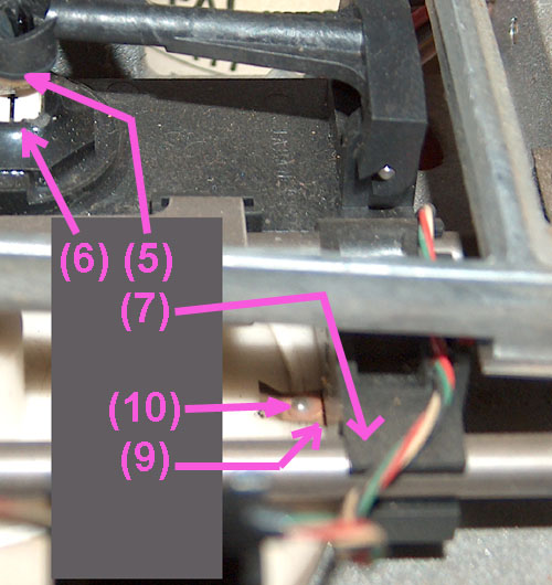
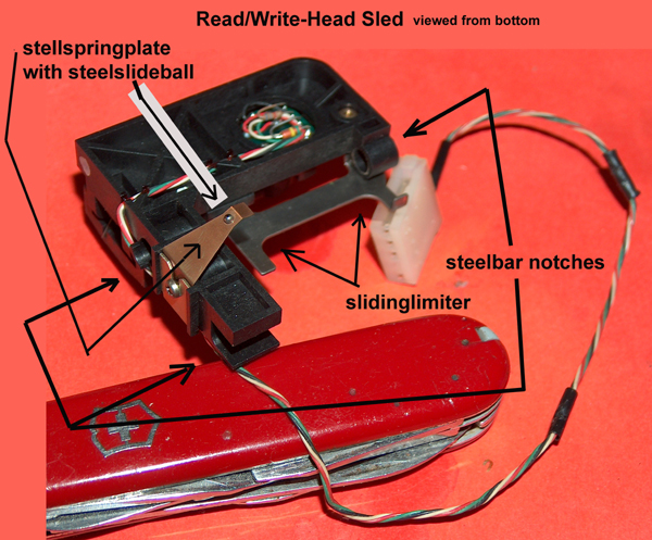
very important: the steelspringplate
(9)
with the
slideball
(10),
and the hardplastic
positioningdisk
(11)
with the guidingnotch for the
slideball (12), and
the slidinglimiter
(13) and
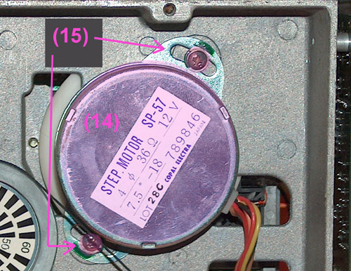
at the bottomside the
positioningsteppermotor
(14)
with its alignment screws
(15). |
 |
| and now the
pictures in detail with the
mentioned parts (1) to (15): |
|
|
|
| |
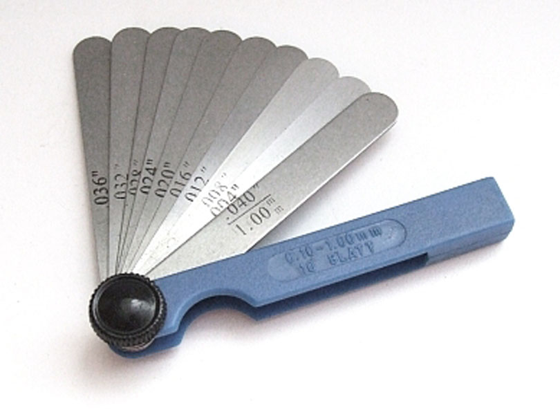
Required
Tools
spacing template
Set with
an .008 to .010 gage steel.
Apple says .010, but
with .008 it will be rather better adjusted.
Such a tool isnīt too expensive and you can get it at
ebay for about $5.
Of course better ones will amount up to $20 but probably
you can lend it from somebody, who is familiar with
repairing himself cars or motorsycles, because this tool
is very common there - its needed to set adjustment at
the mechanic of the ignition-breaker.
Other possibility of substitute will be a small drill
that you know that it has the requested diameter. |
 |
| |
|
|
|
| |
Parts to pay attention to
The numbers are corresponding to the
numbers listed above !
|
|
| |
Dismounting the
Drive
Dismounting
Analogboard
The analogboard is rather simple to dismount: unplug at the front
the cable to the
read/writehead and pay attention not to issue any force to the thin
cables themselve.
The unplug the MotorPCB-cableplug in the center of the rear. Its
a good idea to also
unplug the cable to the controller.
Then you might loosen the 2 screws at the front edges. The
AnalogPCB then will
slide forward toward the front out of the notches of the plastic
Frame.
Finally the drive then should look like this. Deposit the
analogboard on a antistatic foam
or in a antistaticsleeve!
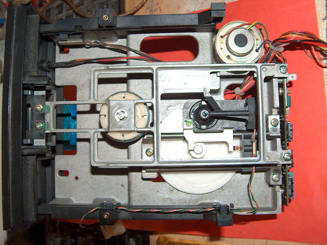
Next will be the dismounting of the topframe. Loosen the 2 screws
at the rearside of the
frame and the frame will slide with the frontdoor of the drive out
of the notches of the
frontpart of the drive. Be carefull at this step and donīt damage
the lever of the toppart
of the sled that carries the diskpushdownfoam.
short remark besides:
the diskpushdowmfoam can become a
source of trouble when using both sides of
a disk.... because if turning around the disk to write at the
opposite side at the same time that material slides
along the side that has been written..... if material became bad it
can scratch the durface of the disk....
so its very important that this material is soft and very clean (
without any kind of dirt ! ). So keep care of this ! |
 |
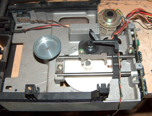
Dismounted Topframe
The next step will be explained besides the next
picture.
First of all the cable to the Read/Write Head should be
removed from the notches of the plasticframe
very gently and carefully without damaging or tearing
with force ! That cables are thin
and very sensitive
to force. |
 |
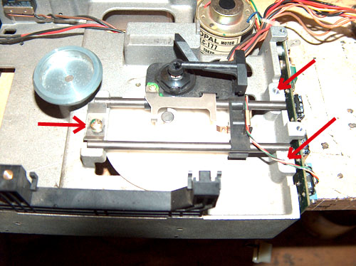
Dismounting Steelbars
In this step the steelbars will
be dismounted. First the 2 screws at the rear of the
drive shall
be loosened and taken out. Then the centering screw
with the centering blade at the front
of the steelbars shall be released.
Then the steelbars can be removed together with the
read/write-head sled and the bars can
be pulled out gently and carefully. Be sure to avoid
any kind of force against the read/writehead
itself and handle this sled with very much care !
Protect the read/write-head from dust or dirt and
deposit it while storage in a antistatic-bag ! |
 |
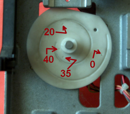
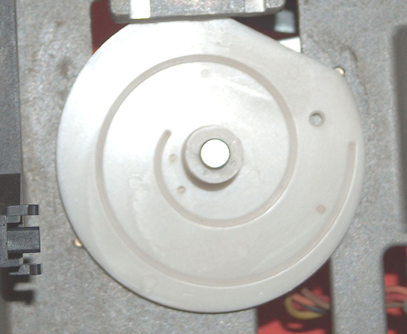
In this stage you will be
able to see the entire positioningdisk - this one is
still uncleaned and i want
to guide your attention to the 4 small spotmarks
drilled into the material. They mark 4 important points
and are from the factory ..... they indicate the
position where the steelball of the steelspringplate
should
be when the sled is positioned to "fixpoints" at
:
track 0
track 20
track 35
track 40.
This indicates that this positioningdisk was
manufactured by a company, that also delivered this disk
to
thirdparty customers that made drives that also
could handle 40 tracks ( as most of the drives could...
),
the limitation to 35 tracks was also in those
days rather unusual and it was related to the fact that
Apple
did not use specialized chips for diskhandling on
their PCBs. So due to the use of standard chips the
use of the "inner 5 tracks" ( with more
compressed data and higher demands to the electronic
read/write
compensation were higher and Apple decided to
stay away from this inner tracks and believed them to
be not safe with the DISKII analogboard. |
 |
|
|
| |
Cleaning and lubbíng the
positioningdisk
In case of doubt please reread the
explenations at page 1. Donīt use aggresive cleaning
fluids !
The positioning disk was cleaned with
isopropanol-alcohol ( 70% ). Be sure to also clean every
bit of dirt out from the sliding-notch ! Then
apply very few grease in the notch and wipe it all
along the entire notch with a Q-Tip. Thereafter clean
again the entire top of the disk with a soft
tissue and just leave the grease within the
glidingnotch. Then the disk should look like the one
in the picture at the right side...... |
 |
and cleaning the Read/WriteHead
Cleaning the read/write-head should
be performed very careful.... avoid any kind of
aggresive
power..... donīt produce scratches
and only use very clean isopropanolalcohol from a
pharmacy
with 70% to 95%. Use a very soft
tissue for cleaning and dry afterwards carefully and
gently.
Then you can start to remount the
drive again. NEVER touch the screw that fixes the
sliding-
limiter ! It is upmost important to
keep this part exactly in the position as it left the
factory !
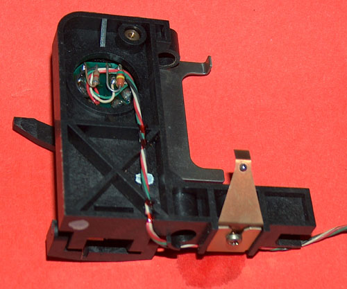
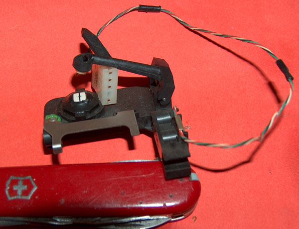
The following pictures are just for
information and display the parts in very detail to
become
familiar with the parts. Recognize
the exact position and view of the steelspringplate !
This is the very part that is
responsible for the positioning of the sled and therefor
extremly
important later when calibrating the
track 0 ! The steelball runs within the guidingnotch of
the
positioningdisk. It might turn out
that the steelspringplate became weak throughout the
years
so its a good idea to bendup that
plate a little ( not too much ! ) to make sure that
later the
steelspringplate will press down the
steelball firmly in the guidingnotch - but not to firm !
If the positioningdisk is turned the
sled must slide gently and perfect forward and backward
- but the steelslideball shall remain
within the notch ! |
 |
|
|
| |
The Read/Write-Headsled
in detail
|
|
| |
Remounting
the drive for alignment
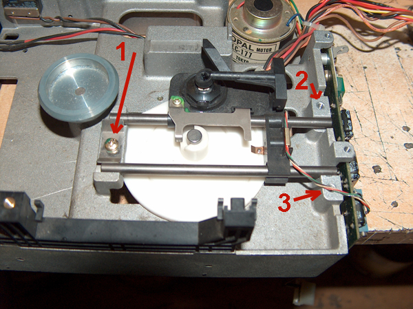
Put the steelbars again back in the correct
position of the sled and apply
a little grease to the steelbars and then just
gently lay the steelbars in the
position of the driveframe - at this moment the
very position of the sled
is not that important. Insert the screw and the
alignmentplate at position 1
and start gently to turn the screw till it gets
grip in the frame..... then gently
tighten the screw - but just that far that you
still can adjust the position/length
of the steelbars to make sure that they are plain
with the backside of the frame.
Maké sure that there is space between the
slidinglimiter and the axis of the
positioningmotor. Now tighten the screw! Next you
should insert the screw and
the fixingplate at position no. 2....... and
tighten that screw. up to this moment
the position of the sled was not important due to
the fact that the sled still is
lifted up at the outer side a liittle bit. But
now you should turn the positioning-
disk till the steelslidingball slips into the
guidingnotch and turning the disk
moves the sled forward and backward. Move the
sled somewhere to the middle
range area and then fix the outer steelbar with
the screw and fixingplate at
position no. 3.
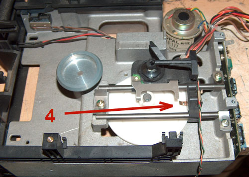
Now turnback the disk clockwise till the sled is
at the rearside and the slideball
is just opposite to the drillmark that i
explained few pictures above to indicate
the position of track 0 like in the picture below
at the right side. |
 |
Text is continued in the next
cell below. |
 |
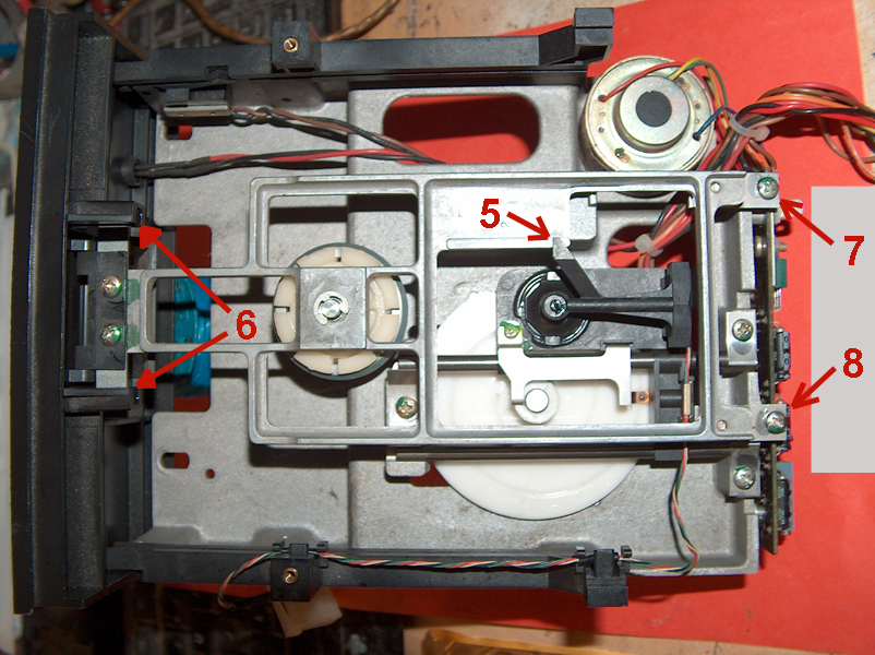
Now we will remount the topframe. Gently let
the door slide into the notches (6)
of the frontpanel and make sure that the door is in horizontal
position to make
sure that the 2 metalclamps donīt block when slightly sliding in
that door in
position ... - then lift up the lever that carries the
diskpushdownfoam so that the
arm of the lever slips to the sliding area (5) of the topframe and
then slide the
topframe gently to the position so that the hole of the rear
steelblades are right
on top above of the desired hole that are determined for the
screws.
Now tighten the screws 7 and 8 and donīt be irritated - when
tightening that
screws the topframe will lift upwards because this is the
purpose of the
steelplates at the end of the topframe. After the screws have
been tightened
you should add a little bit of grease in the notches at
position 5 and 6 and
shut and open the door to make sure that this does not cause noise and
that
the mechanic operates smooth and the door locks gently.
|
 |
|
|
| |
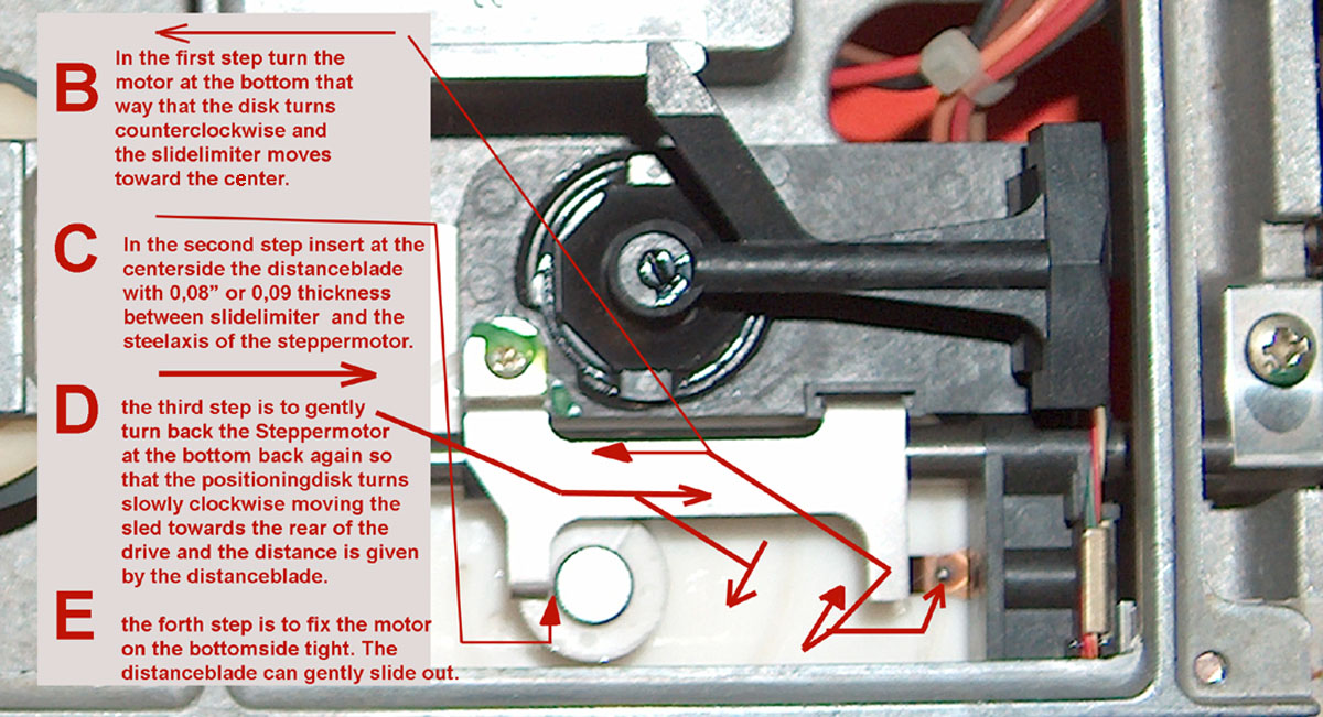
Aligning the Track Zero
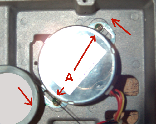
A
- untighten
the screws but leave them in the frame....
they just shall be
unfastened that far that the Steppermotor
can be slided
gently to both directions and thereby turns the
positioningdisk at
the other side smooth.....
then follow the
instructions below.... |
 |
|
|
| |
Final remounting before testing with the software
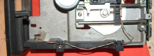
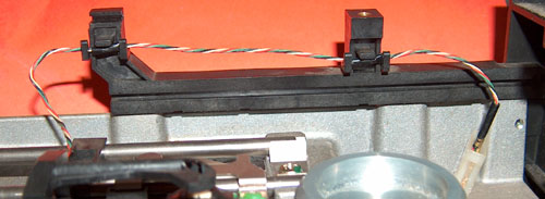
Remount the cable with the wires to the
read/write-head very carefully the
same way as displayed in the pictures at the
right side and take care not to
damage that thin and sensitive cables ! The black
covers should be fixed in
the notches and the cable should slide gently
through that covers.... leave
at the rearside enough cable that permits the
sled to glide along the entire
area without getting force applied to the cable. |
 |
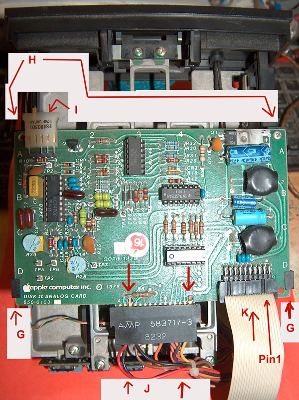
Take the
analogboard and position it in the correct orientation
and then
let the board slide into the notches of the
plasticframe at the positions
G and then fix the screws
at the positions H.
Thereafter plug the read/write-
head cable to the connector at position
I and take care of the
correct
orientation indicated by the missing pol.
Then plugin the connector with the MotorPCB-cables at
position J. Take
care of the plastic lockers marked by the arrows ! Then
plugin the
flatribboncable at position K. Take care that the side
of the cable indicated
by a colorside or with the brown or black
ribbonside is oriented towards the
side indicated in the picture with pin 1.
Remark:
Its a common accident that the
plug of the flatribboncable is pluged
in the wrong way around at the controller and that
kills chips in the electronics !
So it is wise to also mark at this point the cable at
the other side by a
penmarker and mark the side where pin1 is at that plug
at the controllerside
too to avoid such an accident in the future ! |
 |
|
|
| |
Now we are at the point that we can test the adjustment.
If the drive passes the test itīs fine....
otherwise the entire
procedures must be
repeated with the alternating distanceblades.......
Be aware that this test only works with the original disk
and that copies of the
disk or disks generated with ADT wonīt work ! In that
case the only kind of
verification will be, to boot from a disk written by a drive
that is known to be
aligned correct and then write a disk and try to read that
disk completely in the
recommended other drive known to be aligned correct !
|
|
| |
| |
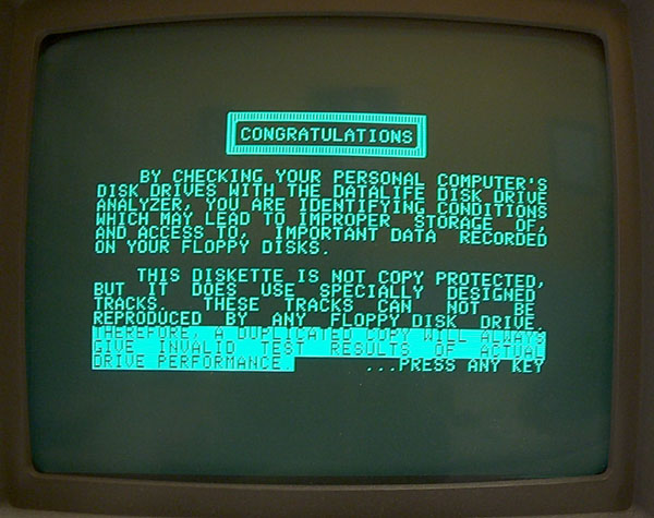
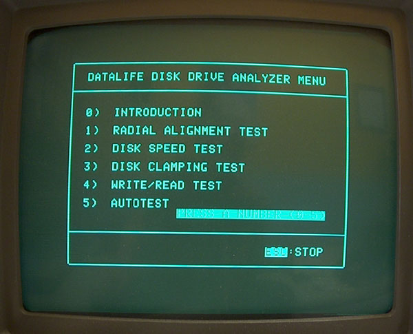
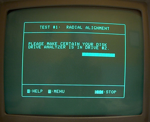
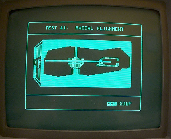
The only software that was released to the public, that
offers a test of
the track zero alignment is from Datalife the "Datalife
Disk Drive Analyzer"
!
|
| |
 |
| |
|
| |
 |
| |
|
| |
 |
| |
|
| |
 |
| |
|
| |
 |
| |
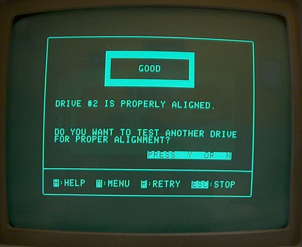
If you went along the above displayed menus and options
and recieved this display - congratulations !
Youīve solved the task successfully !
|
|
|
| |
This Part is related to the topic if
you want to use the oscilloscope instead of the software
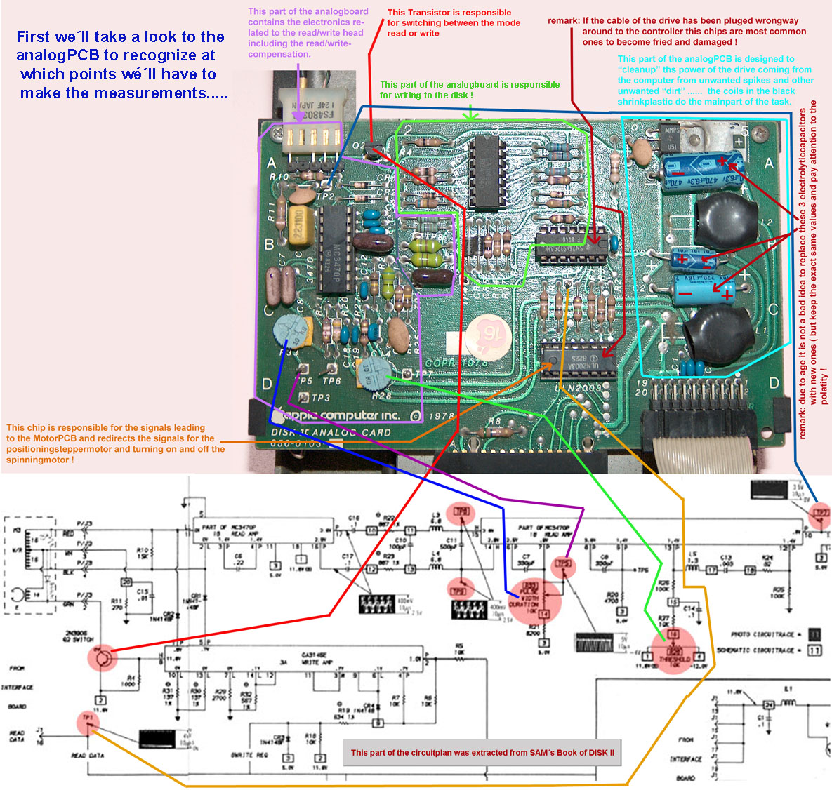 |
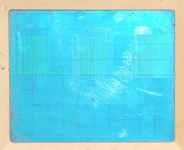
If the Track is
aligned correct the signal measured at Testpoint 2 ( in
the circuitplan at the very right
side ) in the picture of the analog board at the top left ( close
to the read/write head connector )
should look very similar to the picture of the right side.... - if
the alignment is wrong the signal will
have less amplitude and the signal will be "noisy" ( i.e. the
signal wonīt be clear but rather more
"disturbed by spikes" and "rounded edges" at the corners of the
rising and falling edges. Also the
amplutiudes if the single bits will be with "rising" or "falling"
rooftops and the bottomline will be
very "noisy" to because the read/write head will try reading beside
the track....
you might compare this to the driving with a car on the road.....
if the car is on the road the noise-
level will be low.... - but if you leave the road with 2 tires at
one side "off from the road" those
tires will be runnung very noisy in the dirt ! |
 |
| |
|
| |
|
| |
|
| |
|
| |
|
| |
|
|
|
| |
*)
Allthough the DOS ( Disk
Operation System ) from Apple started with diskformat and a
drive that only was able to handle 35 tracks - Steve
Wozniak was aware of the fact, that within a short period of
time drives could be availiable with more than 35 tracks and
that the format of
the disk might change (i.e. like the fact that first
they started with 13 sectors and later changed to 16 sectors )
as it was also performed with
the other larger computer of that days ( remember about
the also common 8" diskdrives with more tracks and more sectors
).... not to forget
that parts of the DOS-system from Apple were similar to
other versions of DOS from those days ( it will go to far at
this moment to tell stories
about the influence of "big
copycat Billy "the Kid" Gates" in the development of the
DOS-version used by Apple ..... thats a story for
insiders... )
Besides the information of the format ao the disk the
track 0 also contains the FAT or at least in one sector the
information
where the FAT is located on the disk ( tracknumber and
sectornumber ... ) - this FAT ( File Allocation Table ) can be
compared to the
roadmap together with a adressbook - and it tells the
computer which file is located in which track and which sectors
and the amount of sectors
used to store the file... if the FAT get larger the
last sector of the track contains information in which track and
sector the FAT is continued....
( this is for example valid for ProDos and there the
track- and sectorinformation is converted to "blocknumbers" )
... but in the days of DOS and
CPM the space granted to the FAT was limited .... this was
one of the reasons that at DOS the size if filenames was limited
in length and the amount
amount of files to be stored was limited to maximum of 96
files regardless if the disk was full or not.....
|
|
| |
download this
page as PDF-file

turnback to page about
speedadjustment of the drive
turnback to page about
basic mantainance of the DISK II
continue to the page about
advanced adjustment of the offset
of the electronical Read/Write-Head compensation cycle
|
|


