|
|
|
|
The Basic
DISK II Pages
|
|
Page
No.:H084-9 |
|
|
|
|
|
|
the DuoDisk
|
|
|
|
|
|
|
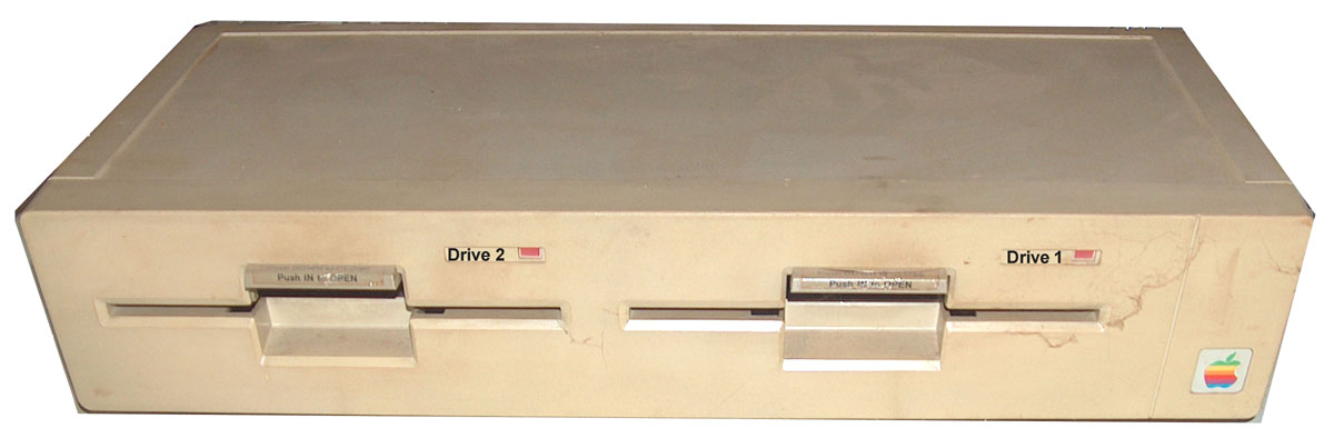
The Duodisk is
added to this chapter related to the fact that this
unit was introduced during the period of the Apple
II+ to the market and the Duodisk was intended to be
the regular sold set of 2 DiskII systems with the
computer. In that days the storage capacity still
was limited by the fact that 1 Floppydisk only
contained 140 kByte of Data and 1 Disk contained the
operation system ( at the right side as Drive 1 )
and maybe a program and the second disk ( as Drive 2
at the left side ) was intended to be used for
storage of the data ( bearing in mind that a long
period of time only diskdrives offered singleside
mechanic ).
Other factors in
that days have been limited by the fast that
important components for the mechanic in that days
have been limited too: The head positioning mechanic
was too expensive and at the time of introduction
the stepping motors got miniaturized and first
stepping motors offered construction of so called "halfheight"
drives saving space and reducing the track problems
still caused by the mechanical positioning of the
read/write head and its mechanical wearout.
This page is focused on the service and splits
in two sections:
first section displays details about mounting /
dismounting the drive and cables as well as locating
the electronic components
and second sections displays the circuitplan and
electronic details comparing the duodisk with the
DISK II. The similarities demands to also read the
previous pages of the DISK II because from view of
the service still a lot of procedures still remain
similar to the former drives.
|
 |
|
|
|
|
|
|
|
|
|
|
|
|
|
The case of the
Duodisk consists with two parts:
the shell for bottom and front - and the shell for
top and upper rearpart.
It contains two
single drives inside, each in a kind of Faraday-cage
- which i call in the further part of the text a "RFI-protection-cage"
( acting as shielding ).
The
internal drives are locked each by 4 screws to the
bottomshell.
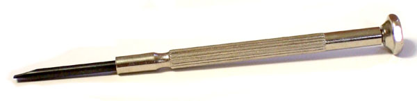
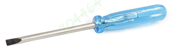
Pay
attention to the 2 small holes in the bottom shell
each for access to the trimmer of the
internal drive tht controls the speed of the drive.
In that case a very small screwdriver is a important
demand and the screwdriver should look a bit
like one of the ones displayed here:
|
 |
|
TIP: to avoid
electronic shortcut between PCB and grounded RFI
protection cage the major part of the metal of the
screwdriver should be covered except a tiny tip of
the screwdriver blade with isolating shrink hose.
The 2 screws at
the rear of the topshell fixe it at the bottomshell
where that topshell is in place by support of the
groove in the bottomshell.
Important
info: the
connector at the rear for the attachment of the
cable from the Computer is
NOT
locked by any screws to the topshell. It is only
locked in its place by screws to the internal cage
of the internal drive!
|
 |
|
At the bottom
each internal driveframe and its bottom
cage is
attached in its position at the bottom part of the
caseshell with four screws to the bottom part of the
outer case. |
 |
Here in this picture at the right side is a view
displayed after the top caseshell has been removed
and you can see the connectors and cables and the
connections within the duodisk.
But keep care to inspect the orientation of the
cables and plugs and their orientation marked by the
colors of the wires. |
 |
|
|
|
|
|
|
|
|
|
|
|
|
|
This section
displays the both parts of the "RFI protection
cage".that cover the internal drive mechanic.
Each bottom
part of the two RFI protection cages is attached at
the alternating sides by two screws to the frame of
the internal drive mechanic.
Before attaching the top part of the RFI-ptotection
cage pay attention to the protection sleves at the
cables that shall protect the cable wires against
contact / shortcuts with the grounded shield cage
and lead then to the outer electronic PCB on top
above the drive 2.
Then the top part of the RFI protection cage is
mounted to the bottom part by slipping into the two
clamps at the bottom part of the RFI protection
cage.
Both RFI-cage
parts must have good and firm electronic contact
with the grounding cable at the rear of the drives
which is attached with screws and lead the grounding
rail to the shielding of the cable connector at the
rear of the duodrive.
|
 |
|
| |
 |
|
| |
 |
|
The picture at the
right side displays at the left top the most
remarkable difference to the DISK II -
the step-motor that is responsible for positioning
of the read/write head to the tracks.
While in the old system a Disk with grove and
gliding
steel-ball (
see page 3 ) was used for movement here now is a
steel-band fixed to the read/writehead to perform
direct movement.
Except the location of the trimmer related to the
speed adjustment the procedure of the speed
adjustment itself is same like explained at
page 2 for the DISK II ! |
 |
|
|
|
|
|
|
|
At this point the section starts that is related to the
electronics
of the Duodisk |
|
|
|
|
|
|
the
Block-shema
The major part of the the electronic at the Duodisk
is similar to the DISK II - the remarkable
difference results to the fact that a set of
electronic switches has been added: That switches
ensure that the signals from the Drivecable at the
rear splits apart in 2 sections and detects to which
internal drive the signals shall be sent - either
Drive 1 - or Drive 2 - but
never
both drives at the same time.
a second
switch just splits between the function at the
MC3470 - either read or write mode.
At the
moment the first switch has not been completely
analyzed. This will be added to this page in a later
stage in several weeks in detail.
At the moment its for service in general important
to publish that parts, that are similar to the DISK
II and the minor differences to that drive.
The color markings and the capitals used in this
block shema are same color and capitals I used in
the following circuitplan and PCB-pictures.
|
 |
|
|
|
|
|
|
|
|
|
|
|
|
|
part of the circuitplan
At part A the circuit is
allocated to the CA3146 and the writecoil within the
Read/Write head responsible for writing data to
disk.
At part B of the plan the MC3470 is responsible for
the amplification and "fashioning" of the signals
from the read-coil reading data from disk.
Part C is buffering and cleaning the supplyvoltage
and shall block spikes of away from the electronics.
Part D and E are sections for
switching between read and write mode and indicating
activity at the drive.
Part F related to the ULN2003 is
responsible for buffering the handshakesignals
between controller and the drives. Similar is valid
to the 74LS125.
The remaining 6 chips that have been left without
colormarking belong to the switching between Drive 1
and Drive 2. |
 |
|
|
|
|
|
|
|
|
|
|
|
|
|
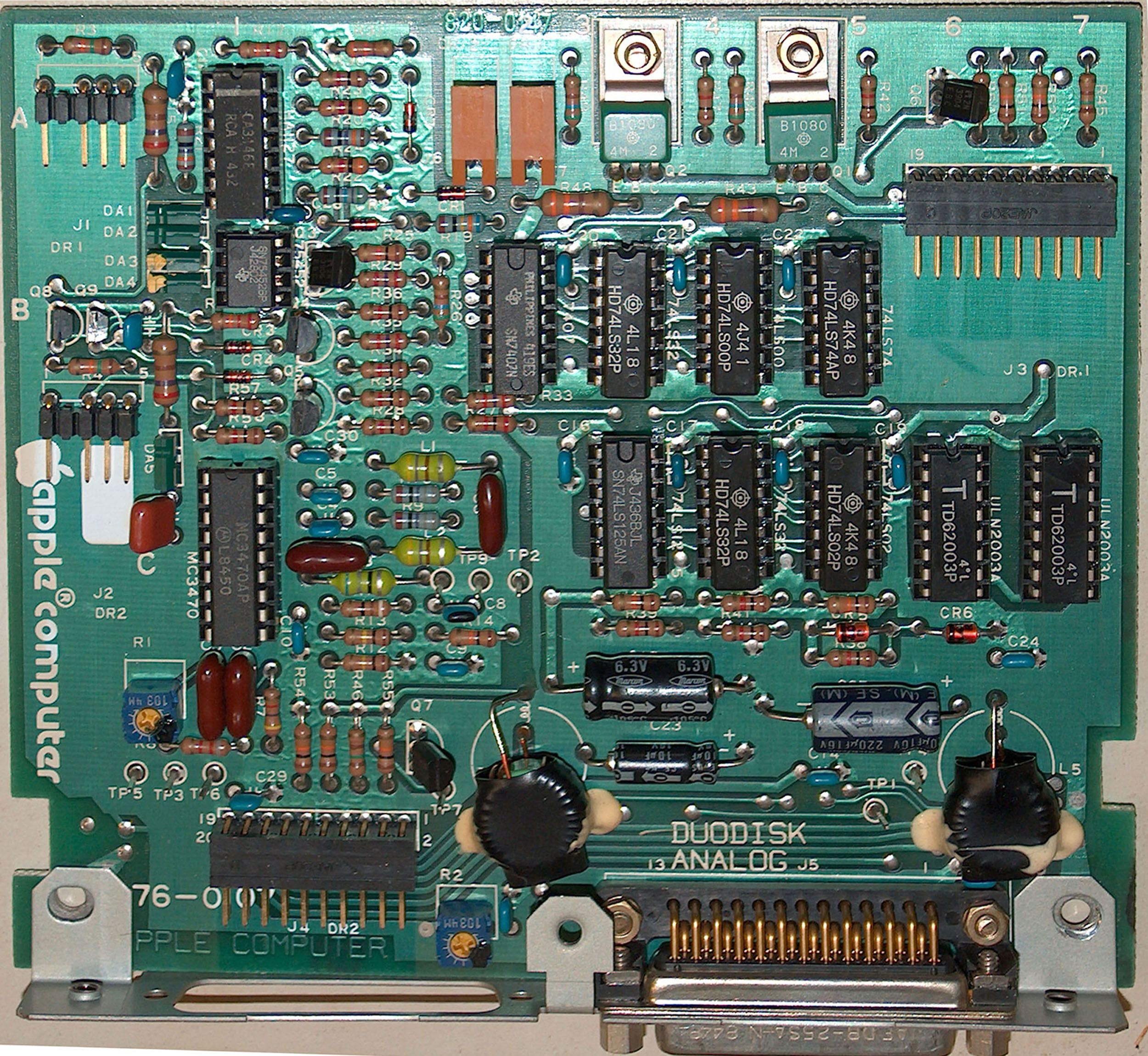
the PCB
At part A the circuit is
allocated to the CA3146 and the writecoil within the
Read/Write head responsible for writing data to
disk.
At part B of the plan the MC3470 is responsible for
the amplification and "fashioning" of the signals
from the read-coil reading data from disk.
Part C is buffering and cleaning the supplyvoltage
and shall block spikes of away from the electronics.
Part D and E are sections for
switching between read and write mode and indicating
activity at the drive.
Part F related to the ULN2003 is
responsible for buffering the handshakesignals
between controller and the drives. Similar is valid
to the 74LS125.
The remaining 6 chips that have been left without
colormarking belong to the switching between Drive 1
and Drive 2.
Beware of the orientation of the missing pins at the
plugs of the Read/Writeheads at the connectors to
Drive 1 and Drive 2 !
|
 |
| |
 |
|
|
|
|
|
|
|
|
|
|
|
|
|
|
|
|
|
|
|
|
|
|
|
|
|
|
|
|
|
|
download this page as PDF-file
 |
|
|
|
|
|
|
|
|
|
|
|
|
|
|
|
|
|
|
|
|
|
|
|
due to european laws
and german court decision:
I hereby declare no responsibility to any "deep links"
resulting from the links in this page. I have no influence
to the pages linked hereby in this page and the
contents in those pages. I therefor can't take any kind of
responsibility to contents in the pages, where these links
direct the readers browser to nor to the
contents resulting from following up links from those
pages. The reference to contents by this links is dependent
ro the status of the date when the links have
been set ( April 2013 ) and it might occur that references
and contents may change by the fact that domains may have
been discontinued from their former owners.
In such cases i can't take any kind of responsibility to
the changed contents. this is specialy valid to banners,
advertisements or merchandising links in the targeted
pages.
|
|