When a Apple IIe system
gets released from a long time
storage it's recommended to examine that system
very
carefully to avoid damage from the involved parts and interface cards. It's strictly recommended to followup
exactly this line of procedures.
One of the reasons for this procedures is to narrow down
possible reasons of malfunction.
That saves a lot of time and besides it also is a kind of
standard routine that helps to detect most of the common
problems that may occur when a system is resurrected.
The very start is to
prepare
the
tests:
Unplug all interface cards and
markup at the card with an adhesive label the slot
where the
card has been unplugged from.
All cards shall be stored in antistatic bags while remaining
unplugged
due to the
fact that quite a lot of that cards
contain static sensitive chips.
Next all chips should be examined if they are inserted with
correct orientation in the sockets. The white silk screen
printing at the mainboard indicates the correct orientation
by display of the notch side from the chip.
There are quite a lot of
different versions of the unenhanced and enhanced IIe model
out there. Due to the fact that most of that computers had
former owners it's a good idea at this moment to detect
which model it is. The first basic point to examine will be
the CPU. If the CPU is a 65C02 there is a good chance that
it is a enhanced //e. But in some cases only the CPU has
been changed and leaving the old ROMs inside - the upgrade
is not complete ! Therefor you should also examine the ROMs
and note the Apple no.s ( 34N-NNNN ). some bad mistake
result from mixing wrong ROMs with each other. Therefor you
schould compare your list with
legal Set-Versions of the ROMs
depending the the language
version.
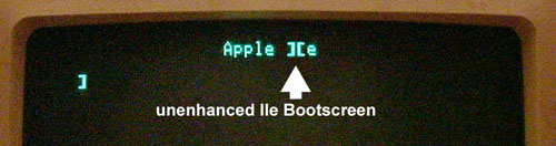
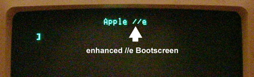
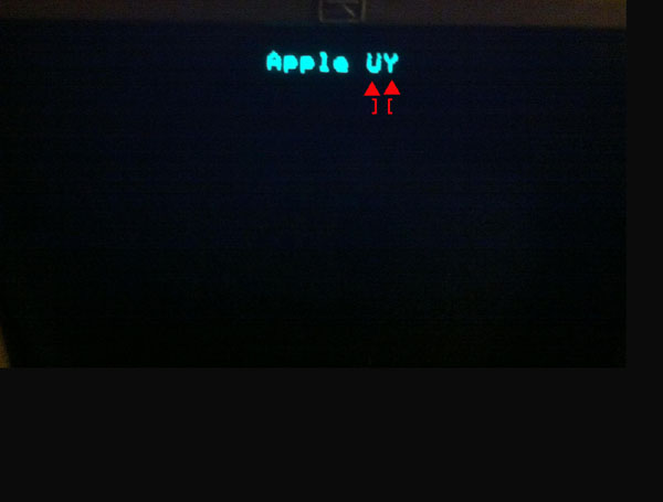
If everything seems to be correct up till now you
may try a firts very short "test.powerup". Pay at
this moment attention and compare the display with
the 2 displays below.
|
| No,
if it's showing "][e" on the boot up, it's not
enhanced. When enhanced it'll show "//e".
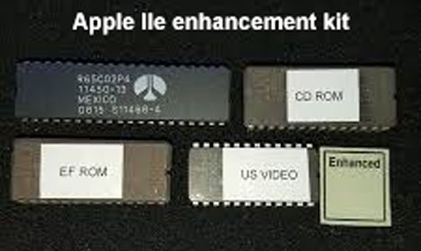
To
enhance one of these you need to replace four
specific ROM chips, and change the CPU from a 6502
to a 65c02. These five chips are collectively known
as the Enhancement Kit.
To run
the built-in self-test,
push both the [open apple] and [closed apple] keys
on startup.
Or if the machine is already running, push [open
apple], [closed apple], and reset.
If the Apple
//e in question is a platinum model, substitute
[closed apple] with the [option] key.
If all is
well, you will get the message of either "KERNEL OK"
(on an unenhanced //e) or "System OK" (on an
enhanced //e); otherwise you will get an error
message indicating what is wrong (Google will be
your friend in this case).
|
| |
| |
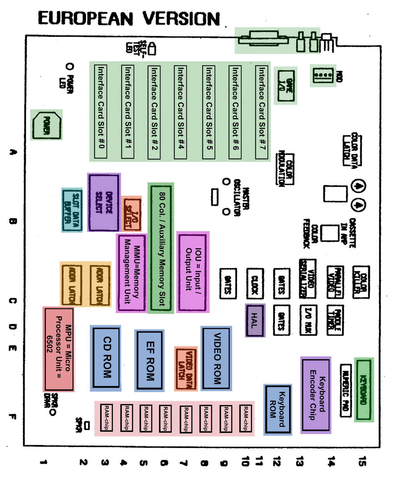
The
most remarkable difference between the previous
Apple II an II+ models and the Apple //e is the
extreme reduction of the amount of used digital
logic chips on the mainboard. Apple performed this
task by replacing those chips and integrating their
functions in so called "LSI" chips ( LSI= Large
Scale Integration )-
Its like a coin---- the situation has two faces:
The advantage: by reducing tha amount of chips the
amount of used electric power became reduced and the
reduction also was an advantage to reliability by
reducing the amount of logic chips that might fail.
The big disadvantage at the other side are the 3
LSI chips themselves. That are so called "Custom
Chips" that have been made only for Apple and never
have been released to public distribution or sale
due to patents - and Apple does not have any spares
anymore. The 3 Custom chips are the
MMU.
the IOU
and the HAL
chip.
Some
additional information about the functions of the chips on board:
The
HAL
chip ( Apple Chip No.: 341-0170-A ) is among the 3
custom chips the smallest LSI chip. It devides the
basic system oscillator frequency of 14 Megahertz to
the lower core frequencies used in the other chips
and signal busses and synchronizes the communication
among the components along that system busses. The
chip is rather sensible and resulting from the small
chip package it also produces rather high
temperature. A damage of this chip will cause a wide
range of malfunctions in the entire system.
The
MMU
chip ( Apple Chip No.: 343-0010-B ) is
responsible for any access to the extra
expanded memory above the 64 Kb limit of the "base"
memory. Bear in mind that the 6502 CPU can only
adress direct that so called "base" memory of 64Kb
that is located on the mainboard. Any additional RAM
that adds up the system to a size beyond the 64 Kb
limit must be mapped in so called page-mode in
chunks of a 16Kb window and that this access is
performed by use of the
MMU
chip ( Memory Management Unit ). That acess
to the expanded additional RAM-Memory is performed
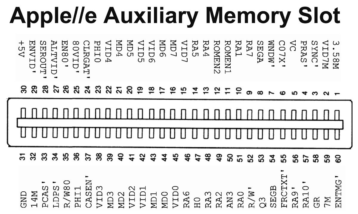
by use of the so called Memory Expansion slot that
also performs the use of the so called 80 column
card for extended text display.
That Memory
expansion slot has other pin connections than
the other 7 expansion
|
slots ! |
 |
|
The
IOU
chip ( Apple Chip No.: 344-0022-A ) ( IOU = Input
Output Unit ) handles the communication between the
mainboard and the teripherial devices - also the
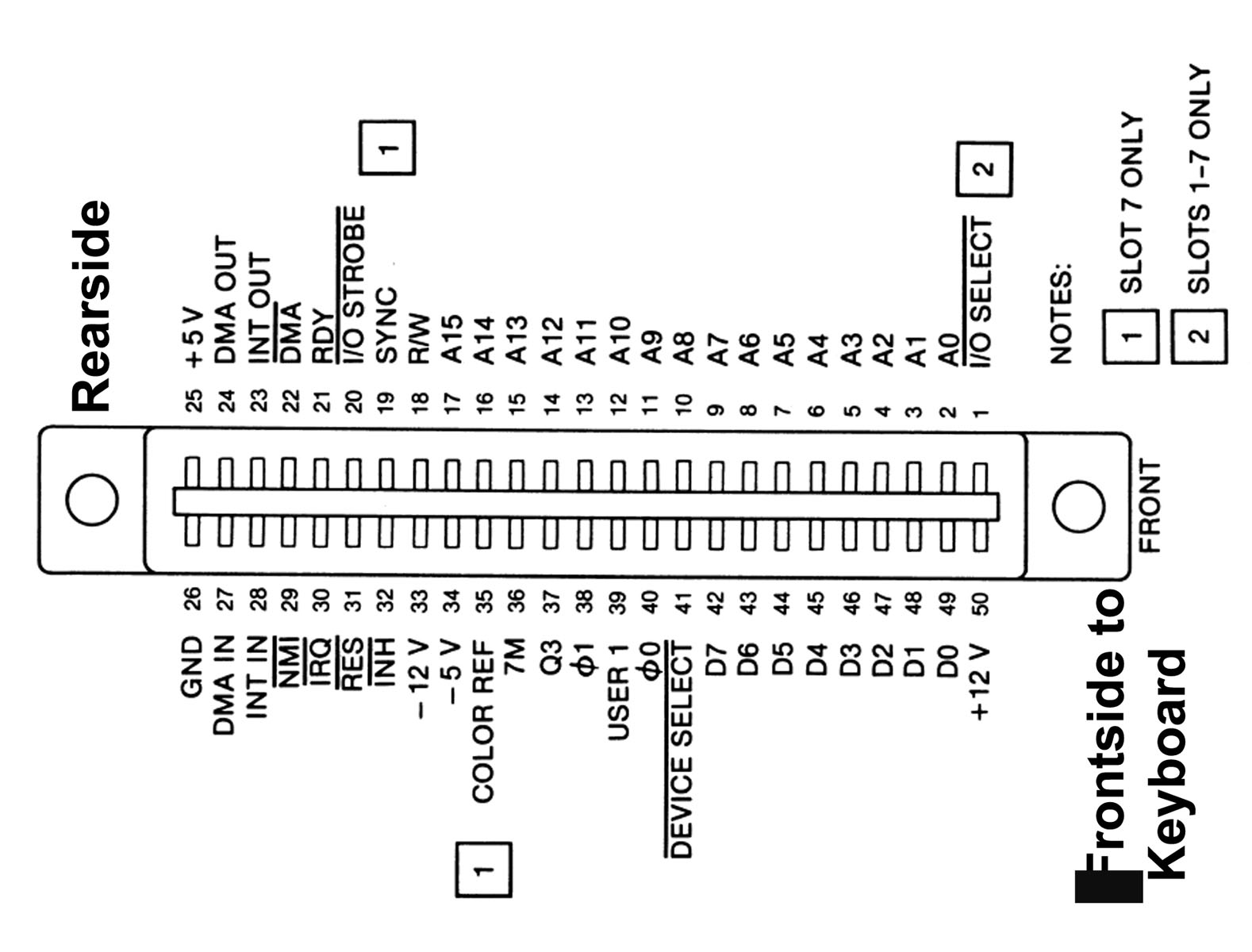
communication by using the seven Interface slots.
The general majority of the signals present at the
seven Interface Card slots are under Control of the
IOU
chip.
|
|
 |
|
The three custom chips like the
HAL-chip
might get destroyed by static schock or static
discharge or by damaged power supply, the
MMU
might get damaged by a demaged 80 Card or a damaged
RAM-expansion card and the
IOU
chip can get killed by a damaged (Interfacecard
inserted in one of the interface expansion slots.
Another reason for damaged power supply can be
caused by heat, to heavy load ( more than 2 disk
drives in daisychain in conjunction with too many
interface cards.
But only in very rare conditions all three custom
chips get killed. In most cases the two other custom
chips survived. So in such case please rescue the
remaining intact custom chips by extracting them and
storing them at a antistatic foam before salvaging
the entire mainboard ! Finally another common Reason
for malfunction is to ignore the guidelines of
handling static sensitive chips at the enhanced //e
and killing the CMOS 65C02
CPU.
|
|
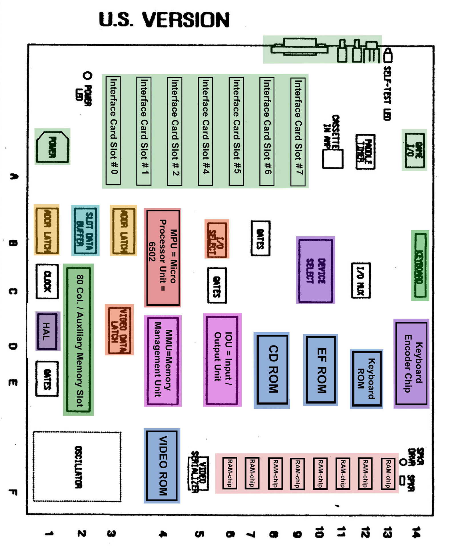
Here sketches of the
basic mainboard versions :
|
|
| |
|
At the Mainboard there is row of RAM chips:
Row 1 is located from
F3
to
F10
and it's responsible for the memory from
0kB to 64 kB.
The rest of the memory from
64 kB
to 128 kB is located
normally inserted in the so called AUX-memory-slot.
For the very beginning of the tests it's recommended to
start with the very basic system
that is required to boot up
to
the prompt at the display:
|
|
This means:
a)
no
interfacecard inserted
b) only
first 64 kB of RAM inserted
c) keyboard is connected to
the mainboard .
|
|
Before we start with the testing
some additional information about the common RAM chips:
It's very strong recommended that
all RAM chips in one row are as similar as possible ( same
kind, same manufacturer ) !
In general all chips have common
kind of marking printed on top of the chip: XX 4164 -nn
XX =
Manufacturer
4116 / some more rare times only 416
-nn = timing
All chips in one row shall be from same manufacturer !
4116-15
for example specifies timing to be certified at
150
nano seconds
4116-2
for example specifies timing to be certified at
200
nano seconds
4116-3
for example specifies timing to be certified at
300
nano seconds
so in that group above the
-15 is
fastest
All RAM chips within one row
must be of same kind of speed !
This rule
overrules the
following
manufacturer rule ! So
first order selection is speed
and second order selection is
manufacturer !
Another point: All chips with rear / front orientation have
pin 1 of the chip at the front ( bottom ) right side and
at that chips counting pins is
counterclock wise
So make sure that at the first row
this general rules are obeyed.
If your rows are containing mixes of different manufacturers
try to get "a clean row" from only one manufacturer.
If you have to order memory from any kind of source try to
get a "clean row" meaning a set of 8 chips from same
manufacturer and same speed !
|
|
So now back to the testing:
Under normal conditions when switching on power at an Apple
IIe with
64 kB of memory ( only one row of
memory plugged in the mainboard ) the
computer should issue
a short beep and then display the message
"APPLE
IIe"
or "Apple//e"
in the top row
centered and the promt "]"
should be at the left side 2 rows
lower blinking and waiting
for input.
|
|
|
| |
|
the result
is:
ram: f13 f12
f11 f10 f9 f8 f7 f6
i
see that diagnostic test, if there is a ram problem,
give something like:
0 0 0 0 0 1 0
0
indicating
which chip is fault,
|
| |
|
Without that,
I would suggest the following:
- Run the
built-in system test by holding Open Apple +
Close Apple while turning power on.
- If SYSTEM
OK,
you may now proceed to next step adding disk drive
controller and 2 drives -
but at this point keep the 80 col card/ Ramcard
still outside of the system and test only with the
testdisks the "base-system" with 64 Kb.
If in this first step with disk drives problems rise
you might read also
this pages.
Only
if system passes all tests with 64 Kb you might
proceed to next second step adding the 80 col. card
and upgrading the system to 128 Kb
repeating tests with the upgraded memory.
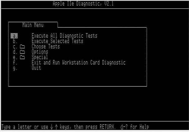
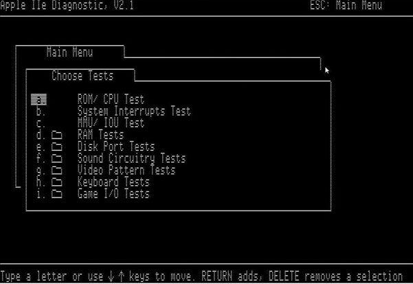
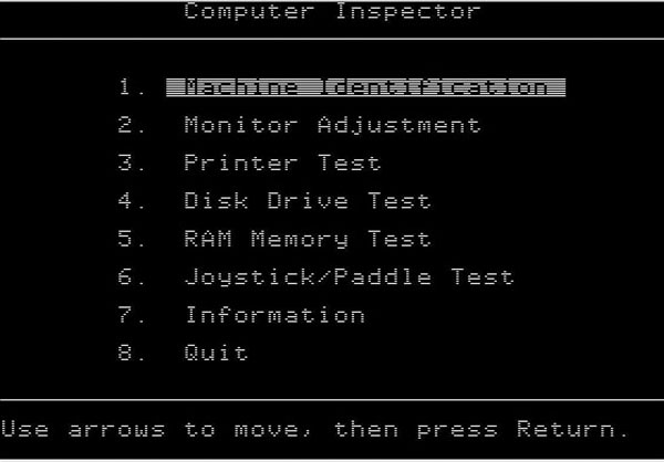
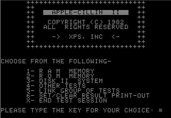
try one of the many diagnostic disks that are
out there:
| |
|
|
|
|
|
|
|
Apple IIe
Diagnostic V2.1. |
|
 |
|
 |
|
 |
|
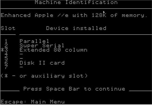
MECC
Computer Inspector |
|
|
|
 |
|
 |
|
Master Diagnostic //e |
|
|
|
|
|
|
|
XPS Diagnostic |
|
|
|
 |
|
 |
| In the case that you do
not have one of this disks look for a friend
that has a working Apple II with working
Disk II drives. Then that person may
download this images and make that disks for
you. The images are for 5,25 double sided
double density floppy disks. After
downloading the images to PC use
ADT or
ADTpro
to generate at the Apple II the Testdisks. |
| |
- If all that
fails, short of having an oscilloscope, the only way
to check a motherboard would be
to replace all chips with those from a known working
logic board. |
| |
If this does not happen the problem may be split in 7 groups
of problems:
1 ) Voltage
In most cases such a mistake will result to
no display at all.
2) CPU
In most cases such a mistake will
result to no display at all.
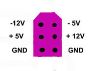
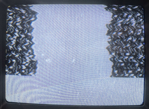
3) Adressingbus
In such a case in general the
display will crash and only display four or eight large
vertical
orientated squares or square bars.
4) Databus
In such a case in general the
display will crash and only display four or eight large
vertical
orientated squares or square bars.
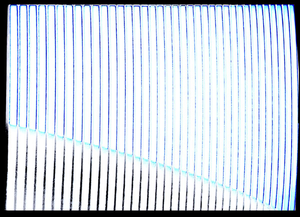
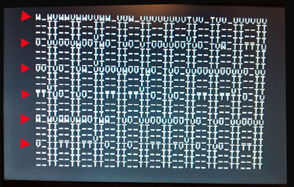
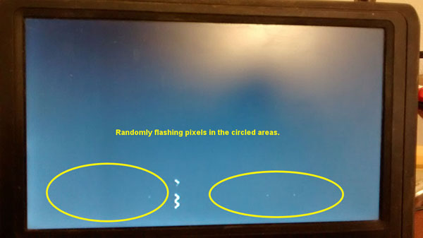
5) RAM chips
In such a case in general you will
get a display of "splashing random characters".
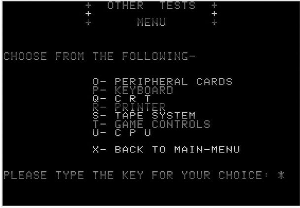
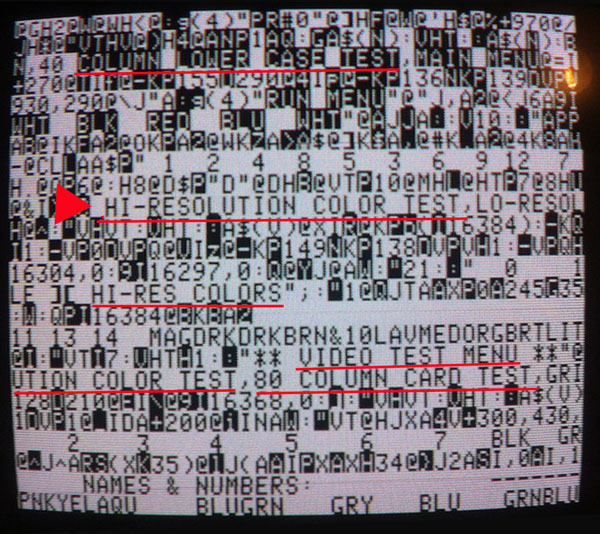
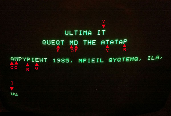
6) ROM chips
If the trouble is caused by the ROM in most cases the
computer will crash to a monitor prompting sign
"*" and
several lines of monitor codes might also be displayed.
=========================================================================
Depending to the kind of error related to the number given
above and to the tools you have availiable
there will be different kinds of
solution to narrow down the problem to a specific chip.
7) other reasons
this will be
treated in a later section.
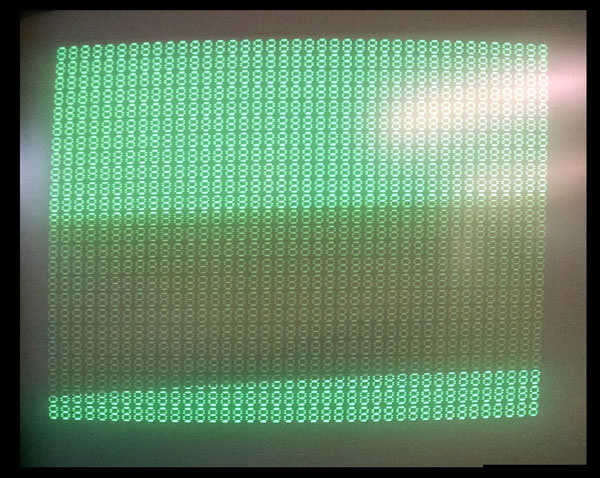
1 )
Well in this case - and it's one of the very first things to
check out - by measuring the voltages direct at the
voltage input plug of the mainboard. You should set your
multimeter to DC 20 Volt.
The black testing cable shall be positioned either at the
left or the right lower ( frontside ) of the powerplug
at the pin marked as Ground. The
red testing cable shall be used for measurements.
It then should display the demanded voltages in a range
within 6% of the specified volts.
- 12,8
Volt to - 11,2 Volt
+ 4,7 Volt to + 5, 3 Volt
|
 |
- 4,7 Volt to
- 5,3 Volt
+ 11,2 Volt to
+ 12,8 Volt |
|
If one of the voltages or more do not match within specified
values the power supply unit must be corrected in next step
to avoid damage to the IC's ! This
is also valid if the power supply unit itself issues unusual
noise or abnormal smell.
In case of smell the problem is normally caused by leaking
electrolytic capacitor. In such case it's recommended to
issue a task called "recapping" the power supply - which is
a term for exchange of the most electrolytic capacitors.
In a few days
i will add / update this page with a detailed description of
this specific task.
If you have an oscilloscope and are a bit experienced it's
also not a bad idea to check the voltages at various
measurement points
in the front rows
B and C
and hunt for so called "spikes" that may disturb randomly
the function of the computer and indicate that
a capacitor is not any more within
its specified limits of ESR value.
http://www.applefritter.com/?q=content/apple-power-supply-capacitor
additional
information about powersupplies at:
http://www.appleii-box.de/D04_allabotpowersupplies.htm
2)
In case of a damaged CPU there is
only one solution: exchange of the CPU and replacement of
the damaged IC.
It's recommended to use for replacement -if possible - a CPU
of same kind ( type and manufacturer ).
3)
In case of adressing port
malfunction one or more of the 3 adressing port chips
4)
In case of trouble with the databus
there are 4 sources of trouble possible:
5)
In case of this kind of trouble you
might swap chip by chip one RAM chip .
6)
If a ROM is bad in general the
adresses displayed in the previous line before the monitor
prompt are within a similar range.
Just for a hint of interpretation what trouble causes which
kind of screen.....
Here some common "crash" boot screens and explenation of the
related problems below that screenshot:
| |
 |
|
 |
|
| |
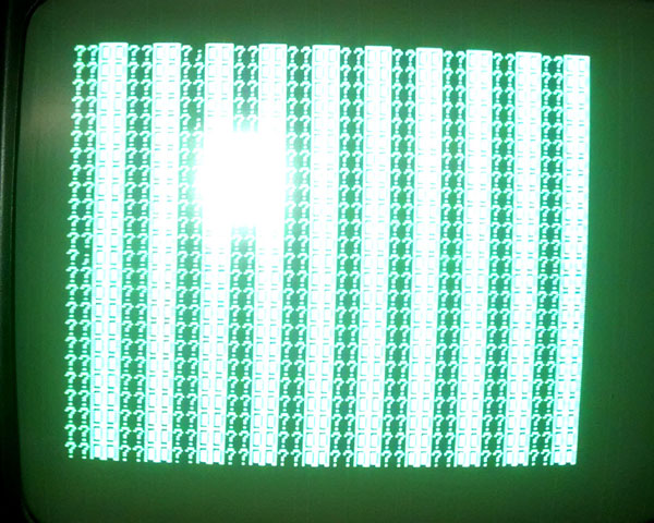
This kind of screen or
similar black/white screen is displayed in very
early bootup stage if adressing line or dataline is
not working. This kind of mistake is not related to
a single RAM chip but rather more to the chips
controlling the data- or adressing busses ! It's not
even able to display the characters so also that bus
between Char ROM and RAM is also affected. |
|
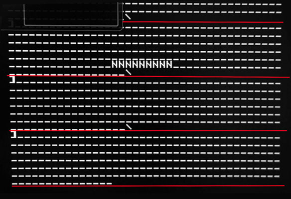
This kind of
screen or similar black/white screen is displayed in
very early bootup stage if adressing line or
dataline is not working. This kind of mistake is not
related to a single RAM chip but rather more to the
chips controlling the data- or adressing busses !
It's able to display the characters so that bus
between Char ROM and RAM is OK. |
|
| |
 |
|
 |
|
| |
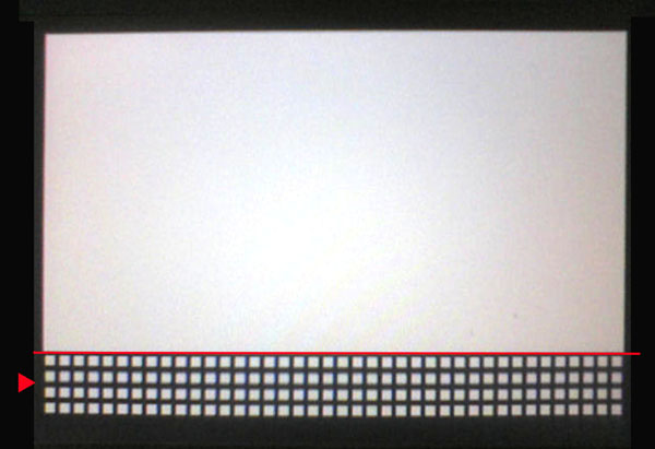
This kind of screen or
similar black/white screen is displayed in later
bootup stage if adressing line or dataline is not
working. This kind of mistake is not related to a
single RAM chip but rather more to the chips
controlling the data- or adressing busses ! It's not
even able to display the characters so also that bus
between Char ROM and RAM is also affected. In such
case it's in most cases related to the Databus and
not the adressingbus. |
|
This kind of
screen or similar black/white screen is displayed in
later bootup stage if adressing line or dataline is
not working. This kind of mistake might be related
to a single RAM chip - but rather more it's related
to the chips controlling the data- or adressing
busses ! In such case it's in most cases
related to the Databus and not the adressingbus. |
|
| |
 |
|
 |
|
| |
This kind of screen or
similar black/white screen is displayed in later
bootup stage if adressing line or dataline is not
working. This kind of mistake might be related to a
single RAM chip - but rather more it's related to
the chips controlling the data- or adressing busses
! In such case it's in most cases related to
the Databus and not the adressingbus. |
|
This kind of
screen appears if the bootup procedure is nearly
completed
- but a stuck key feeds the computer input permanent
preventing the
systems to finish and remain at the promt waiting
for input. |
|
| |
 |
|
 |
|
| |
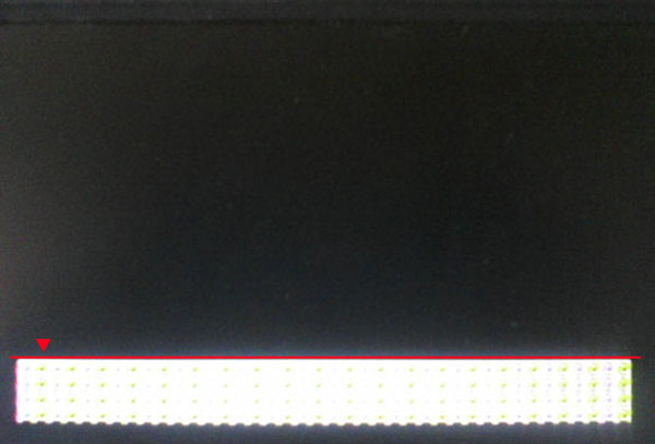
This is a display related
to a rather early crash to the Low resolution
graphics screen.
It's rather often related to trouble at the Data or
adressing bus lines. |
|
This is a
display related to a rather early crash to the Low
resolution graphics screen.
It's rather often related to trouble at the Data or
adressing bus lines. |
|
| |
 |
|
 |
|
| |
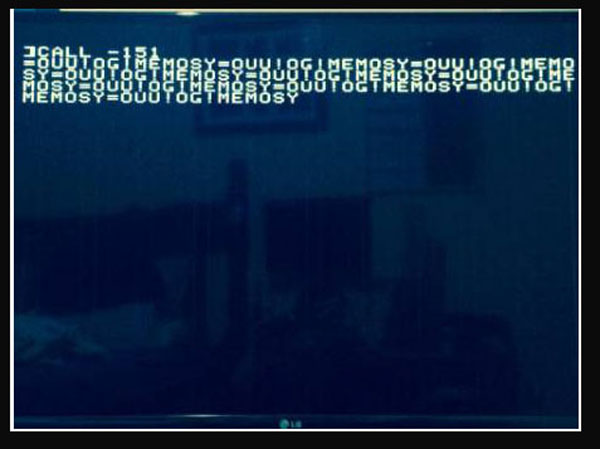
This kind of crash to
memory in monitor mode might occur if a programm
crashes to bad RAM by "out of memory"-error and some
similar kind of screen may also apear if the system
crashes resulting from damaged ROM. |
|
This is a
crash related to later after bootup when a program
crashes to a crashscreen. |
|
| |
 |
|
 |
|
| |
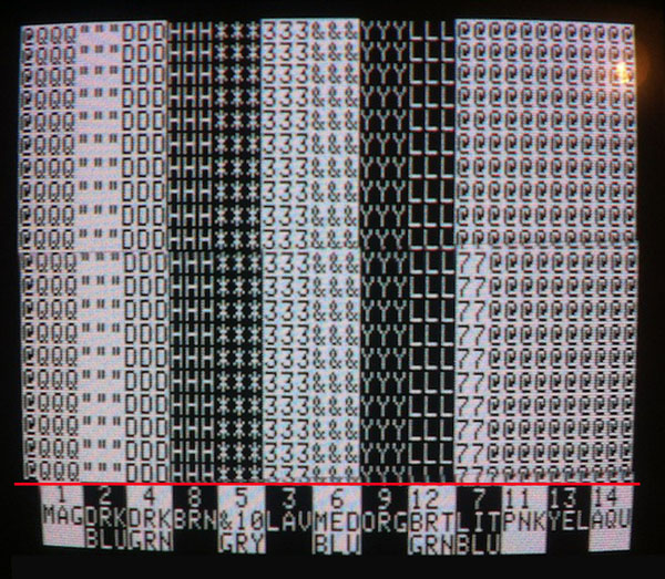
This kind of display may
show after bootup is completed when starting a game
with hires screen and if there is a bad RAM chip
within the second or third row of RAM that is
containing the Hires drawings of the game. |
|
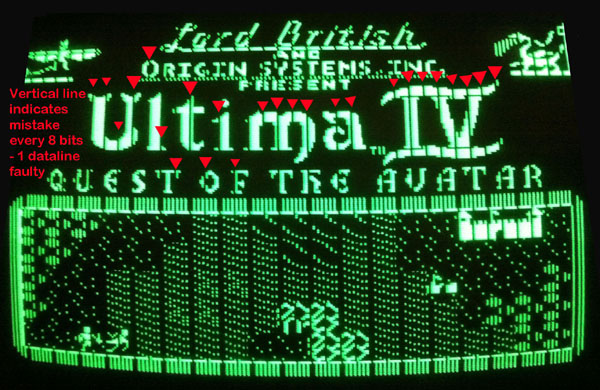
This kind of
screen appears after bootup has completed - but the
access to the character ROM is disturbed or damaged
and text get's displayed with wrong characters. |
|
| |
 |
|
 |
|
| |
This is a problem commen
at the German Apple europlus:
It's displayed if the Apple II europlus has the
German Character Rom inserted without a switch that
eneables to choose between US and German characters. |
|
This screen is
displayed if the 72LS02 at position B14 is damaged. |
|
| |
 |
|
 |
|
| |
This kind of display may
show after bootup is completed when starting a game
with hires screen and if there is a bad RAM chip
within the second or third row of RAM that is
containing the Hires drawings of the game. |
|
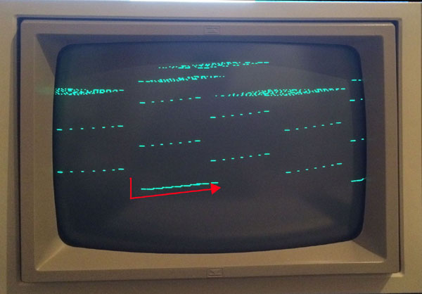
This is
displayed if the Monitor can't catch the vertical
Sync-signal within the videosignal.
In most cases it can be solved by adjusting at the
Monitor. |
|
| |
|
|
|
|
| |
|
|
|
|
7)
This section will be added at later date
If the Computer starts up regular and displays prompt:
The next step after this will be to add the diskcontroller
to slot 6 and try to boot from disk !
First try to boot the DOS masterdisk or a ProDOS master
disk.
Next if you have a testing disk like the dealers confidence
disk or a Master testdisk or a testdisk from XPS then you
should
run all tests including the memory
tests
then the keyboard test
the display test
the ROM tests.
Before adding additional cards it's
also recommended to check the function and speed of the
attached diskdrives.
This kind of procedures is
explained at
this pages and it's follow up pages.
Then you may start adding the
remaining cards step by step to their slots
preferrably to their default slots:
sloot 0 allready occupied by
languagecard or 16 kB RAM card.
slot 1 =>
Printer Interface card
slot 2 => Serial or
super serial
interface card
slot 3 =>
80
column card
slot 4 =>
Z80
CPU / CPM card or alternating CPU card.
slot 5 => soundcard or
additional card for storage (
RAMdisk card, Controller for Harddisk IDE or SCSI or
second disk controller card )
slot 6 allready occupied by
diskcontroller
slot 7 => special videocard or
RGB card or additional card for
RAMdisk or Harddisk interface.
|