|
|
|
Besides explaining
basics about soldering i also will talk about aiding
material and
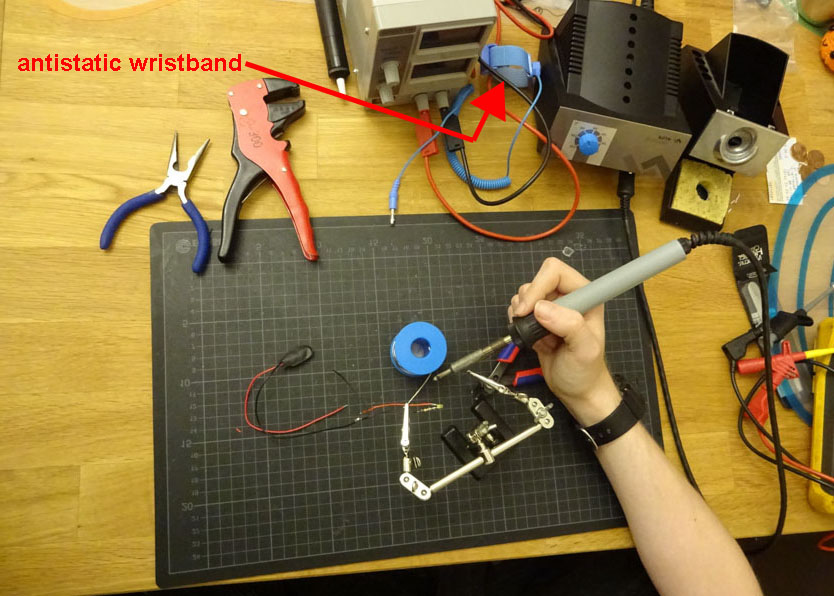
a bit about physics...... the picture at the right side is just an
example of a working
area .... but it gives a good idea about the quality of the light that is
required in the
working area.....
It's also a good idea to place a antistatic protective pad in the area
and you also
should have a antistatic wristband in the area - in case that you work
with static
sensitive devices.....
I have for example covered the entire area at my workspace with natural
cork pad.
Cork has several positive qualities..... it is antistatic and it also is
resistant against
fire and heat and it's soft and there for also protects against
scratches.....
In later parts of
the page you will see several recommended aids that
will be added
sooner or later to the working area.
|
 |
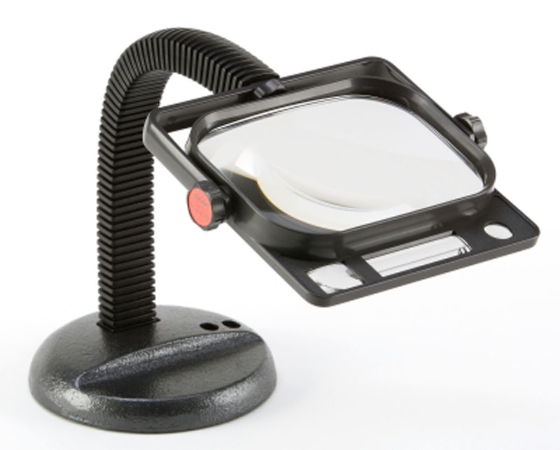
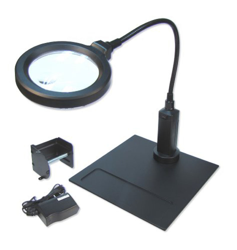
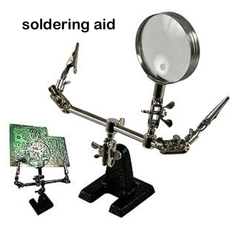
One of that aids will be a
large magnifying glass. Simple ones are without
integrated
lighting. The enlargement factor should be at least twice but in most
cases that
large workspace magnifying glasses offer a factor of 3,0 to 3,5
enlargement.
It should have a stabile footing ( really heavy ! ) or it should offer
the chance to be
attached with clamps to the table. If not you need to use a hand to
hold that device
while the hand should be available for the soldering task !
The alternate is wearing a kind of magnifying goggles. It's a
matter of taste what kind
of solution you will prefer..... the first option draws higher cast while
the second option
is cheaper....
The first option restricts the magnification to limited area at
workspace while the
remaining
areas will be viewed in normal size ... the second
option affects the entire
view...... ( maybe difficult for reading papers aside )
the really
expensive solutions of the first option offer
integrated lighting of the
workspace......
|
  |
|
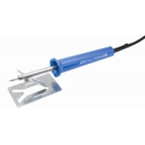
The very simple soldering
irons are rather cheap and offered in a wide rage
beginning at
20 Watt up to 150 Watt. Those useable for soldering at PCB's are beginning
at 25 Watt up
to maximum of 45 Watt. Stronger soldering irons are not recommended due to
the fact
that often that kind of strong irons cause more damage than satisfying
results.
The biggest disadvantage of that kind of cheap soldering irons do not
offer regulation
of temperature. The best range of temperature for soldering is between 290
degrees
Celsius and 380 degrees Celsius. Temperatures above that limit do cause
serious
harms to the PCB's and the components !
This kind of
soldering irons often operate at temperatures
betweens 450 degrees
Celsius up to 500 degrees Celsius ! Besides that high temperatures also
cause an effect
at the tip that is called "scale" a special kind of oxydation. This causes
the soldering tin
not to flow correct and the tip losses fast it's material as burned
coal.... so the tips must
be replaced often within short periods..... after a short while you will
spend that much
money for wasted tips ( say about 10 of the tips ) and spoiled soldering
tin that the total
amount will exceed the amount that you would have spent for a soldering
iron with
temperature regulation !
In every case a
soldering iron should always be placed at a safe
deposit stand when not
used !
|
 |
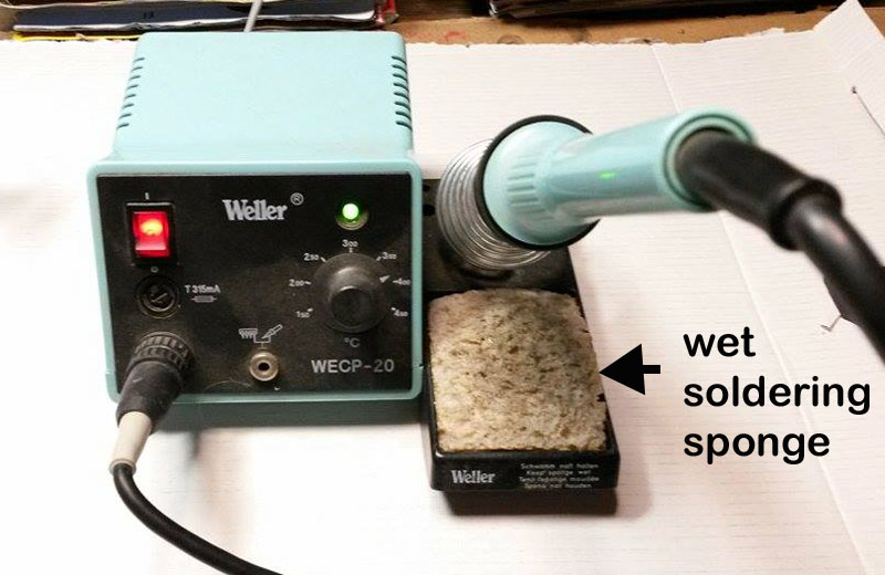
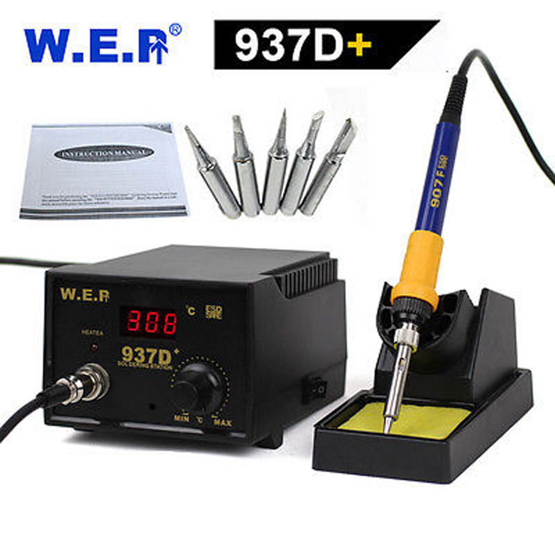
The cheaper soldering irons with regulated temperature use for regulation
a simple
knob with mark pointing to the scale at the front-plate while the better
and only a bit
more expensive stations display the temperature by a digital display. The
difference
is relevant !
While the simple ones are only once scaled and calibrated at the factory
before the
station is distributed to the reseller or store and then by time and drift
that display
drifts off the expected value by up to 10 % - at the other side the those
with digital
display show the temperature in degrees Celsius that is really present at
the tip of
the soldering iron ! This ensures that the temperature regulation is far
more accurate !
The sponge at the
deposit stand of the soldering iron is not just for
fun at that place.
It's for cleaning off the exceeding soldering tin from the tip and keeping
the soldering
tip clean. It's there for a demanded habit to keep care that the sponge is
soaked with
water before you start with a soldering session ad then the amount of
water too much
in the sponge is wringed out !
In general that regulated soldering irons have a power class of 50 Watt to
65 Watt.
This does not matter because the exceeding power won't arrive at the
tip..... it is
prevented by the regulation ---- the reason is just to ensure that the
heating procedure
is fixed to short periods. |
 |
| |
|
| The
better soldering iron stations offer for the
soldering iron tips made with use of
ceramic.
That kind of tips have a nearly endless lifetime...... They can only
become damaged
by mechanical force and not by temperature and they are far more easy to
be kept
clean.
The perfect
temperature is not a fixed point..... it's a
"floating compromise" of different
factors at a current matching point from the following factors:
Size of junction
size of diameter of soldering tin
specific kind of component
- the larger the junction the higher the demanded temperature
|
Average
temperature dependent to size of soldering
area in square mm : |
|
2
mm
2 |
4
mm
2 |
10
mm
2 |
30
mm
2 |
50
mm
2 |
100
mm
2 |
|
320
o
C |
340
o
C |
360
o
C |
380
o
C |
400
o
C |
420
o
C |
|
- the
thicker the diameter of the soldering tin wire the
higher the demanded Temperature
|
Average
temperature dependent to diameter
�
of soldering tin in mm: |
|
diameter
0,5 mm |
diameter
0,7 mm |
diameter
1,0 mm |
diameter
1,5 mm |
diameter
2,0 mm |
diameter
2,5 mm |
|
330
o
C |
340
o
C |
360
o
C |
375
o
C |
390
o
C |
405
o
C |
|
|
 |
|
|
|
- the more sensitive the
component against temperature damage the less higher
the
demanded temperature
( in some cases it's even mandatory to use self-fixing
tweezers to lead temperature
away from component that shall be soldered.... )
|
Average
temperature dependent to temperature
sensitive device ( datasheet ): |
|
CMOS IC or
Diode |
Standard TTL
or
plastic covered capacitors |
transistors or
resistors |
large ceramic
resistors
TO-220 Transistors |
steel nut |
|
310
o
C |
340
o
C |
350
o
C |
360
o
C |
430
o
C |
|
Just for orientation : The temperature used in
general soldering tasks should be above
340 degrees Celsius but below 375 degrees Celsius. But in some cases it's
required to
exceed that limit below to 310 degrees or up to high limit of 430 degrees
Celsius.
One of the major rules is: Keep
temparature in that range that the soldering tin
gets
liquid within 2 seconds and the Joint is finished within maximum
period of another
added 5
seconds.
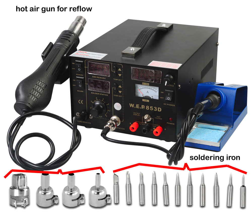
The station
displayed here at the right side is a professional
tool that also permits performance of enhanced
"reflow" jobs like:
adjusting small SMD parts or
extraction
of SMD parts from a PCB or
refixing a
large scale SMD Chip to a PCB or
clean
extraction of sockets from PCB's.
At this
point ( page ) i won't treat this topic - but i will
add another page related to that topic within next
weeks.
But if you intend to only buy once in lifetime a
excellent tool and be sure also to handle later
advanced tasks
like
working with SMD parts it's worth a thought to spend
40 or 50 bucks more for a station that also offers
the additional "hot air gun". In this class of tools
the temperature displayed and set is regulated by
digital control
and measurement at the tip and thereby this tools
are very precise and professional. In general this
tool stations
also use ceramic soldering tips at the soldering
iron.
|
 |
|
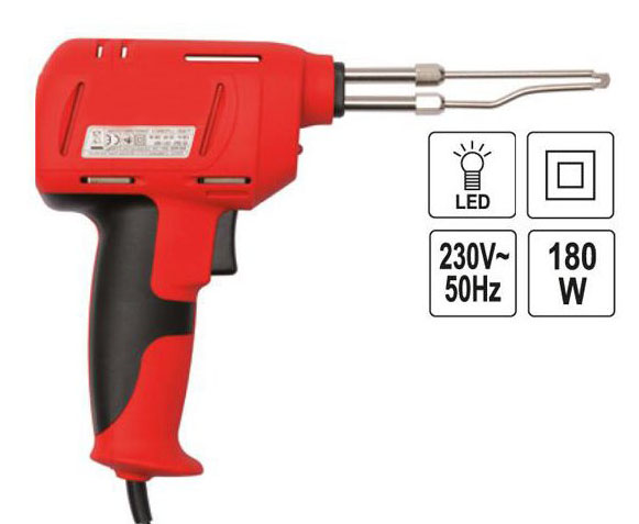
In general such a "heat bullit"
like the soldering gun displayed at the right side
in this row is for regular hobbyist a complete wrong
decision / investment ! This kind of soldering guns
apply far to much heat in the soldering area and
damage more the components by "frying" them -
than solve the soldering job !
There are only very few
cases where such a tool really is a mandatory
option:
- for example if you want to solder steel nuts to a
PCB as mounting junctions for transistors in TO-3
case
- or if you make circuits
with very high radio or satellite frequencies
and want to make a copper case
operating as "Farady cage" to protect the circuit from emitting high
frequencies in surrounding areas
or receive such signals.
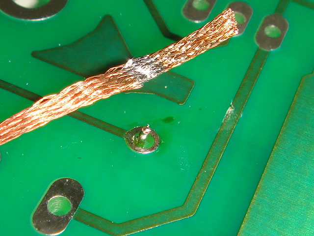
- or soldering
very thick cables (
thicker than 4 square
millimeters ! )
At normal PCB's there is no
kind of job that should be performed by such a tool
!
In general the hobbyist should
have the following aids available at the place
where soldering jobs are performed:
|
 |
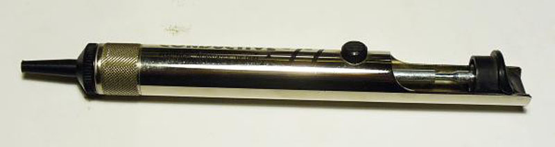
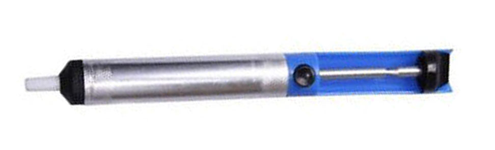
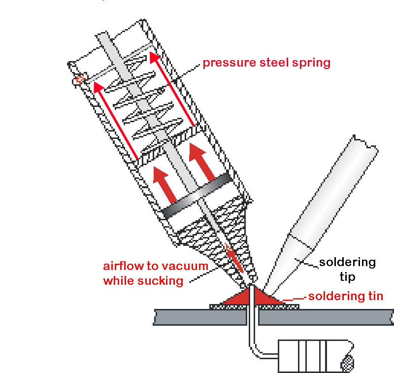
- a desoldering vacuum pump
- a solid stand to deposit the
soldering iron while doing other tasks between
soldering
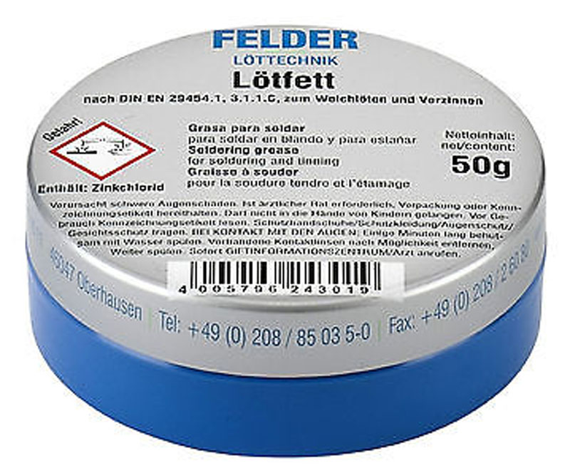
- some kind of flux addon
like soldering grease ( will
be treated later in the this page )
- at least 2 or 3 different
kinds of soldering tin with different diameters:
1 roll with 0,5 or
0,7 mm ( for very tiny soldering jobs )
1 roll with 1,0 or 1,5 mm ( for most soldering jobs )
1 roll with 2mm or
thicker ( for very large soldering jobs )
and if performing high
performance / high quality jobs:
1 roll of soldering tin containing with silver instead of lead
remark: the size of the jobs are related to
the size of soldering area and not to amount of
soldering joints ! |
|
|
At the soldering iron there
are in general two kinds of soldering tips:
the "pen" , "pencil" or
"pin" typ tips similar to the kind of tip displayed
at the top of the right sided picture that put the
heat at a point
or
the "flat" kinds of tip
that put the heat in a larger area like displayed at
the right as lower drawing.
If the user has the option to choose among different
variations of tips fitting to his soldering iron
best choices will be�2 kinds of pencil-tips one with
very tiny tip and one with rather more rounded tip
and one flat tip with "width" of the "blade" of
about 3 to 4 mm.
If this 2 or 3 kinds of tips are present then he
might also try to get a kind of "spade" tip with
width of 5mm to 6 mm. |
|
Another valuable aid is the
"third hand stand".
While performing a soldering job usually both hands
are "occupied":
- one hand with the soldering iron applying the heat
to the soldering area
- one hand with the roll of
soldering tin that applies the soldering tin to the
soldering area.
So it's handy to have a kind of stand that fixes the
"work-piece" or the soldering "items" ( like wires )
in "working position" - and
if that stand also offers a small magnifying glass
to ensure a go view
( slightly enlarged ) to the "working area" - then
even the better !
The problem is that most of this kind of "aids" are
rather cheap and there for rather "limited"....
They don't have a firm
stand.... that might be solved by adding a larger
heavy metal plate at the
bottom of the stand with 2K-glue.
The "holding clips" are not that strong to hold
larger or more heavy pieces ..... this might be
solved by replacing that clamps with stronger
versions......
or the other alternate
solution is the use of a solid or heavy jaw vise and
a separate magnifying glass.
|
 |
|
Not specific related to the
topic at Applefritter - but still interesting to
that guys that make attempt to perform
soldering jobs on own tasks
... In general it's a handicap that soldering jobs
"offside" away from the workbench
are quite difficult to handle because there is no
plug socket to the powersource.......
In such cases there are 2
solutions:
A soldering iron driven by lighter gas
or
a soldering iron driven by
battery or accumulator.
I'm no fan of the ones running on gas .... they are
rather unsafe and expensive and you often have to
refill them...
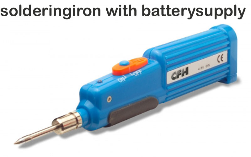
That's the reason i prefer
those running on battery.... like the one displayed
here at the right. It operates with 4
1,5 Volt AAA-typ batteries and if you use alkaline
batteries they have rather good work time ( up to 45
minutes )...
but you can also run them
with AAA accumulator-batteries ( NiMg ) and that's a
good solution to the environment
because then the solution is rechargeable and a
second set of accumulators extends working period.
This enables the experienced user to perform
soldering jobs outdoors for example at the car....
|
 |
|
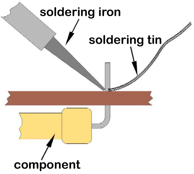
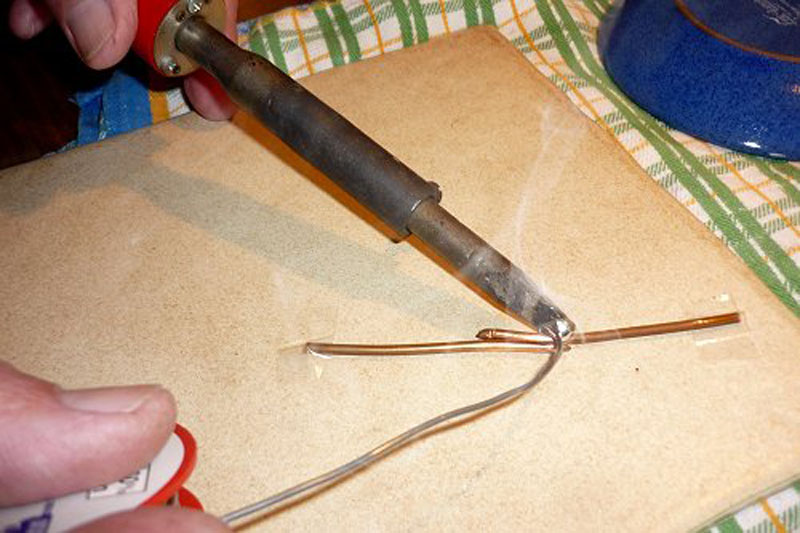
Here a basic description how
to solve the task of soldering:
First place the tip of the
soldering iron at the component that shall be
soldered and apply heat to the wire of the component
( that's a kind of "pre-heating" ) and after about
half a second holding the soldering tin close to the
soldering item so that it starts melting at the wire
or the tip and the flowing down to the soldering
joint and flowing
also inside of the "eye" of the soldering joint.
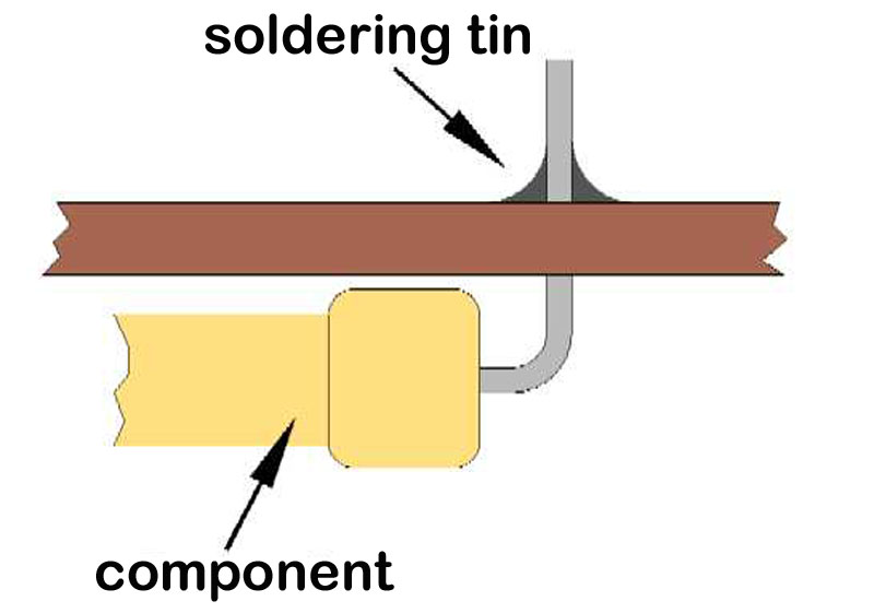
Then after enough soldering
tin has been applied to the point take away the roll
of soldering tin and then after another half of a
second also draw away the soldering tip !
There are several things to pay attention:
Don't put too much soldering tin in the soldering
area - but enough that soldering tin also flows
inside of the junction hole !
Don't waste too much time at the soldering
junction.... just enough to get the soldering tin
melting smooth and flowing smooth to the soldering
area. Avoid to apply too much heat to the component
!
It's a compromise of heat and timing... in case of
doubt hotter tip and shorter time is better than
less hot tip and extended time ! In later picture I
will explain this by displaying bad results and the
reason for such bad results. |
  |
|
If you are a true novice to
the task of soldering it's a good habit to first
gather some exercise at the desk with
some wires before
performing attempt to real PCB tasks.
There is a important reason
for this kind of exercise: Training at blank wires
is not time critical at all - so the novice
has plenty time to collect experience without need
of being ruled by time issues! And by collecting
experience the user may learn step by step to add
speed to his action without taking risk of damaging
components or PCB !
The second advantage by
this method is that the user may perform experiments
by timing and temperature to collect experience and
"get the feeling for correct
timing" between "pre-heating
the soldering area" - "melting
and adding the correct amount" of soldering
tin without "flooding the
soldering area with too much soldering material"
and collecting
"the
correct feeling at what point of time to drag away
the heating source ( the soldering iron )"
and waiting for the soldering junction to drop
temperature and get hard and reliable contact.
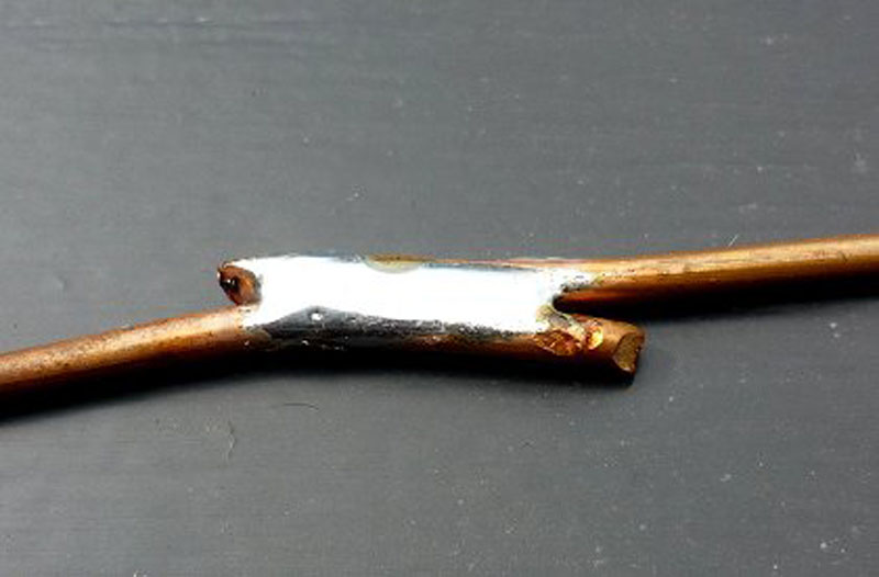
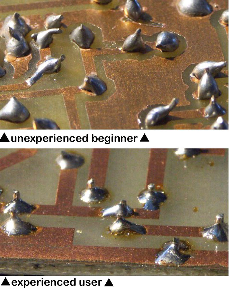
The next picture displays one side of a perfect
junction and at your desk you should be able to view
a same result at both sides of the wire junction
like this picture ! And you should at least have
made 10 such Junctions without mistake
to be sure that your result is
not a "lucky punch" but rather more a result
from collected experience !
|
 |
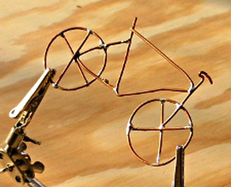
In the following picture below
you see the "model" of a bicycle....
Of course it's just a "gimmick" - but at this point
it expands the demand to your abilities, because it
demands higher skills and advanced recognition
to your timing still without taking risk to damage
real components....
You can't expand the time
of applying heat that much like in earlier
exercises.... otherwise you take risk of weakening
other soldered junctions that you have soldered
previously......
you collect experience with
use of the "third hand aid" or positioning items
previously ahead of the soldering task
- but avoid to add to much pressure to the items
that shall be soldered and avoid dislocating the
items and by that
expanding the gap between the items.
You must learn to keep items that shall be soldered
together as close as possible together and thereby
minimizing the gap and reducing the required amount
of soldering tin to the soldering area to minimum
amount possible.
For this kind of "Gimmicks"
you should use 1,0 mm thick copper wire and later
also try the use of 0,5 mm thick copper wire. As
"Gimmicks" you might try a model of a car or
aeroplane or a boat depending to the item that gives
you most fun....
While performing this
task of soldering wire models it's a good idea also
to exercise "bad habits" like exceeding the time of
soldering too much....
Watch how the characteristics of the soldering tin
change if you remain too long period at the
soldering area or how the time shortens down with
change of this characteristics by higher temperature
! |
 |
The reason is that inside of
the soldering tin there is a tiny core with
additives that permit the soldering tin
to melt smooth and run in smooth fluid condition and
then the soldering tin gets "sticky"
and looses it's
ability to flow smooth.... it starts to stick
at the soldering tip and starts to "glue
like chewing gum" and
looses it's ability to flow instantly......
get the feeling for the
soldering material you use and the
correct timing and avoid in later exercises to
exceed your timing and avoid that your soldering tin
gets "sticky" !
If you stay later too long period or have wrong
temperature the soldering tin won't flow into the
PCB hole
and it won't flow smooth in the soldering area.
Collect experience to recognize such state "by
sight" and
learn to avoid this "state"
otherwise you take risk to 2 kinds of damage: you
might harm the components
by exposing them too much time to the heat of the
soldering iron and the "bonding" of the items will
turn bad....
and besides this effects at aged PCB's you take risk
that traces may loose contact to the PCB and tear
off !
You must be aware that "bonding" ( glue attachment )
between PCB and the copperlayer was not that
good like nowadays... the adhesive power between PCB
and copper layer of early PCB's isn't that strong.
That's also a reason that you must learn to keep
each soldering task within
it's optimum of timeframe. That's also the
reason to also perform some exercise soldering at
damaged new PCB's from the
recycling yard before you
start attempts to solder at old PCB's !
|
 |
|
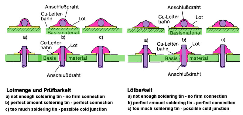
Besides some drawings that display common mistakes
made while soldering.
But far better than drawings such mistakes may be
recognized by viewing the following pictures and
comparing them to the view of correct soldering jobs
! |
 |
|
In next step you may
perform step ahead from PCB with simple large PCB
traces and PCB holes at single sided or double sided
PCB's towards PCB's with far thinner traces and
smaller soldering joints.
It's a step ahead shortening time of soldering and
speeding up your task ! Every step ahead in this row
of exercises forces you to speed up your tasks and
keeping your soldering time long enough to get the
soldering tin flowing correct in the soldering area
and then "leave the place of action" as soon as
possible without taking risk to produce so called
"cold soldering junction". It's slowly training your
abilities by collecting experience and by that also
acquire the ability to judge the correct timing by
instinctively "feeling the
individual need" of each specific junction. |
 |
| |
 |
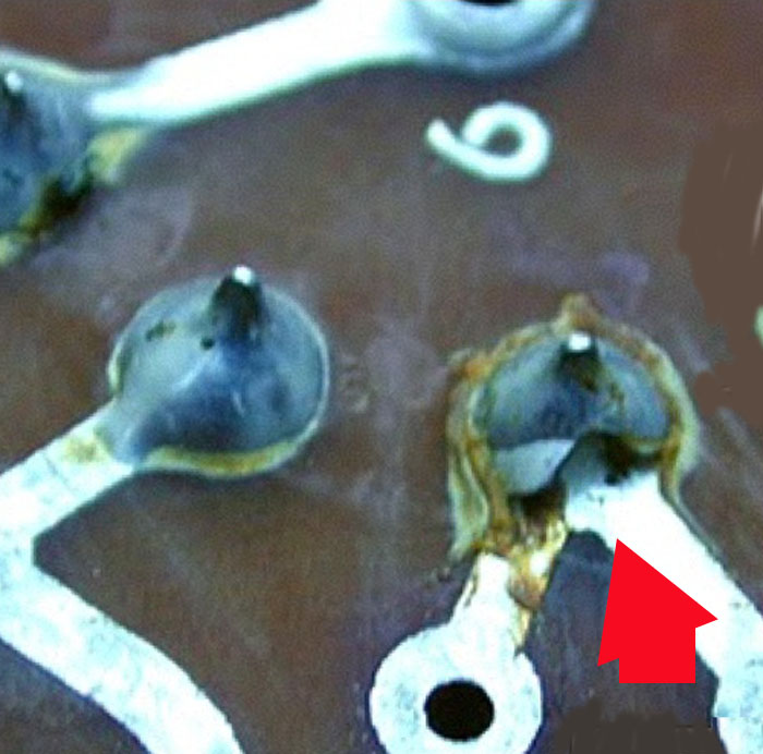
This is a view to a classic so called "cold
soldering junction" where the soldering tin did not
get correct connection with the trace
due to the fact that the soldering time was too
short or the temperature was too low ! |
 |
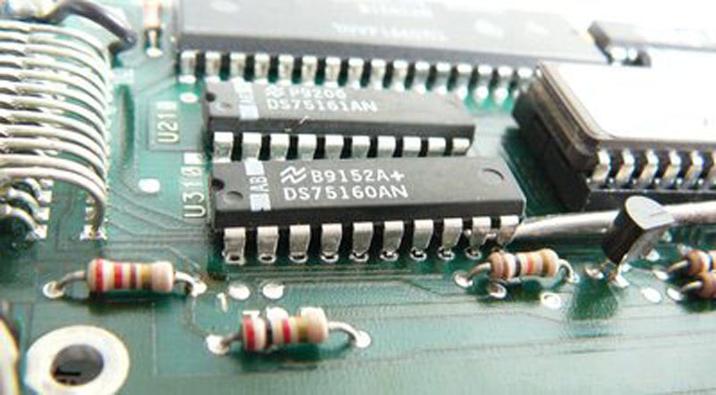
|
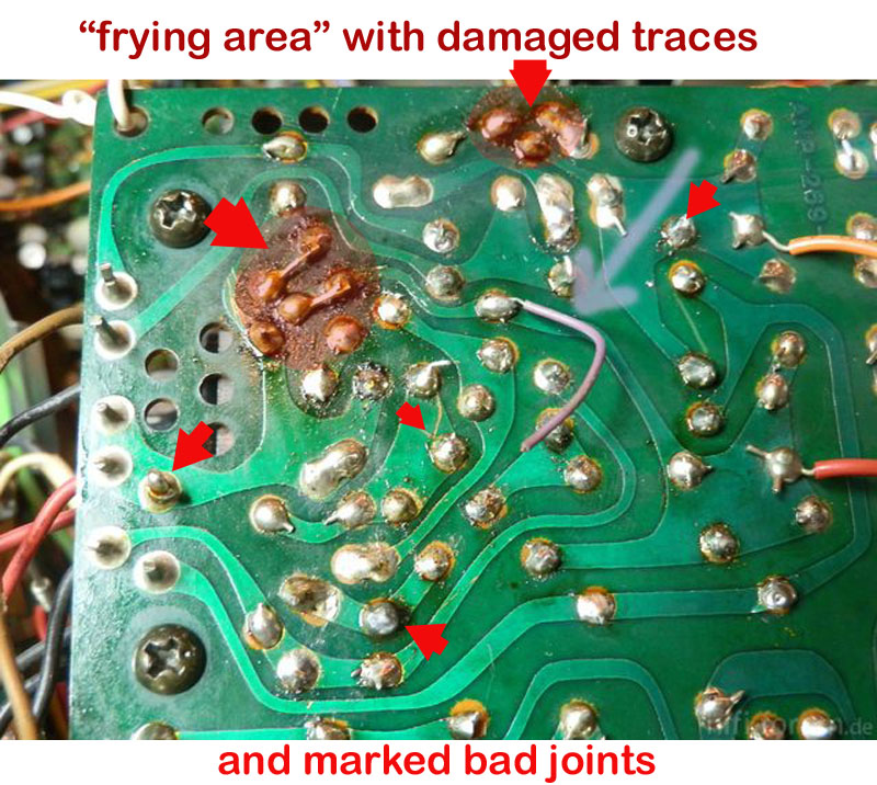
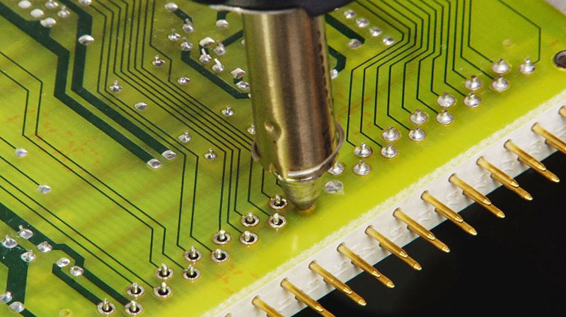
And this PCB display various mistakes ... among also
the mistake of "frying" the PCB and thereby damaging
the trace resulting to the fact that the trace went
off the PCB and needed to be replaced by wire......
the change in the color of the PCB is typical
indicator of such BBQ-parties ! Ad besides it's also
rather sure that the related components have been
damaged too by the BBQ ! |
 |
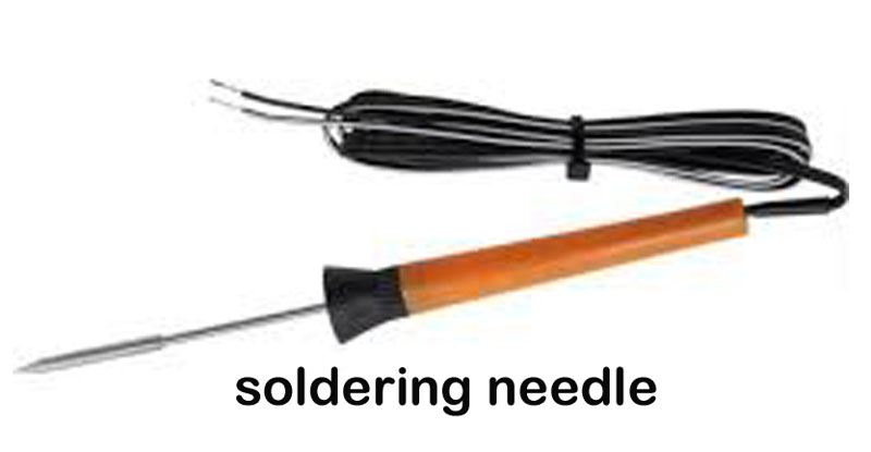
A special case is the use of the so called
"soldering needle"..... That a mini-
ature soldering iron for use with 12 Volt and it's
size is comparable to a normal pencil !
It's "heating power" is limited to average 10 Watt
to 15 Watt. But that's far enough to heat up the
very tiny tip to 360 degrees Celsius to 380 degrees
Celsius !
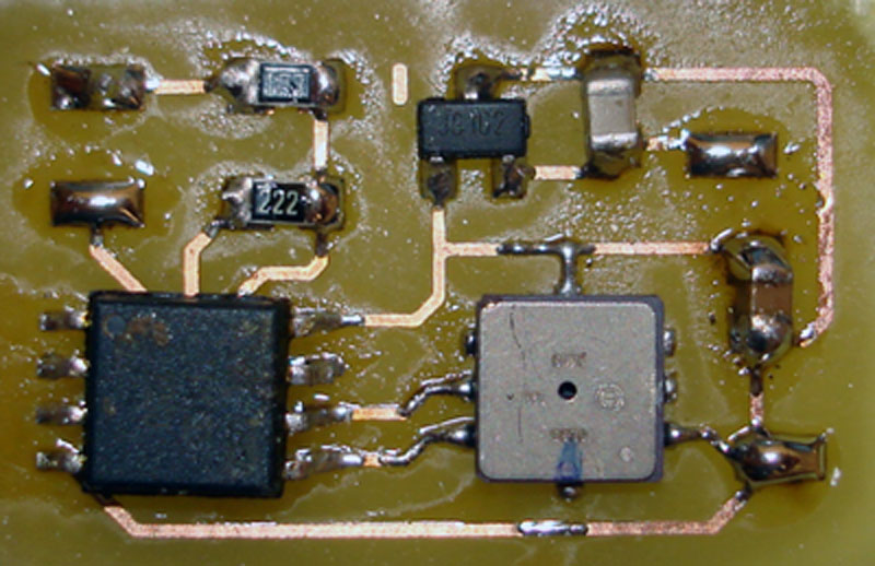
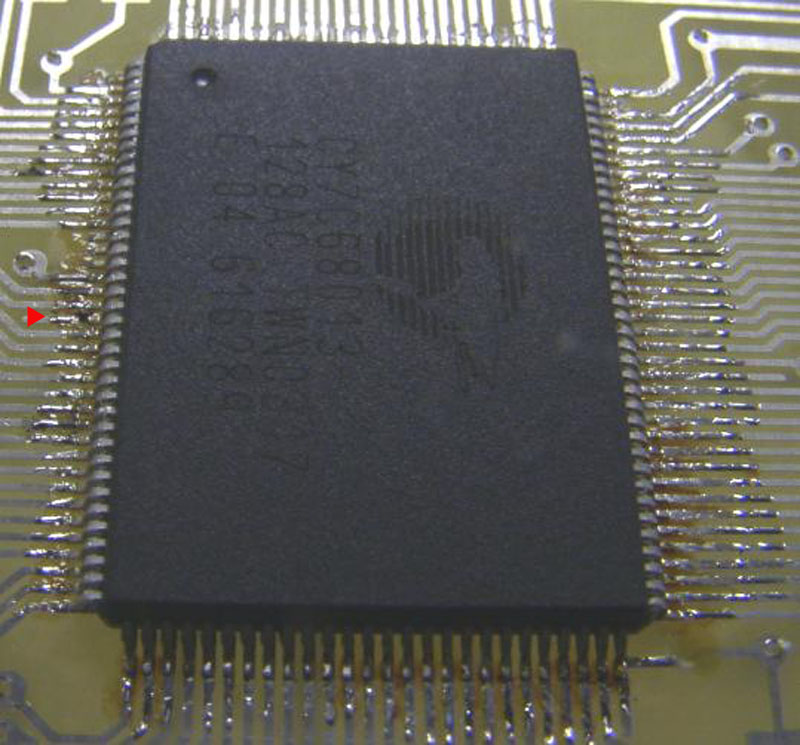
Just to get an impression: at old PCB's the traces
had a width of 2 mm to 2,5 mm. In modern PCB's the
traces at so called "Very High Compressed Devices"
in SMD- technology are only with widths of 0,17 mm !
The next picture in the following row displays such
a device and such a device can only be soldered
either by a reflow device ( see such a station with
"hot air gun" at upper part of the page ) or by use
of such a "soldering needle" ! |
 |
In such tasks it also
is mandatory that while performing such a task a
"oversize" magnifying glass is used !
This is a soldering job really only for very
experienced users ! |
 |
Here
we start about the topic
of de-soldering ! |
|
The user might face the need of desoldering
components by different reasons....
just some examples:
- a ancients PCB contains some obsolete components
that not not obtainable any more ( even not from
resellers at recycling yards )
- the PCB contains a component that has been made as
unique individual part
- the part is still intact in a
damaged PCB and the part was unfortunately very very
expensive.....
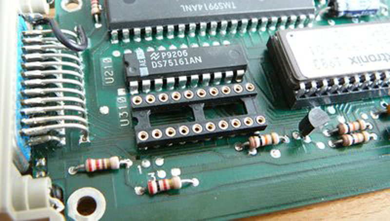
In such cases the user is
lucky if that components are located in a socket....
but according to Murphy's
law all parts that you need are soldered and that
parts you don't need are placed in sockets.....
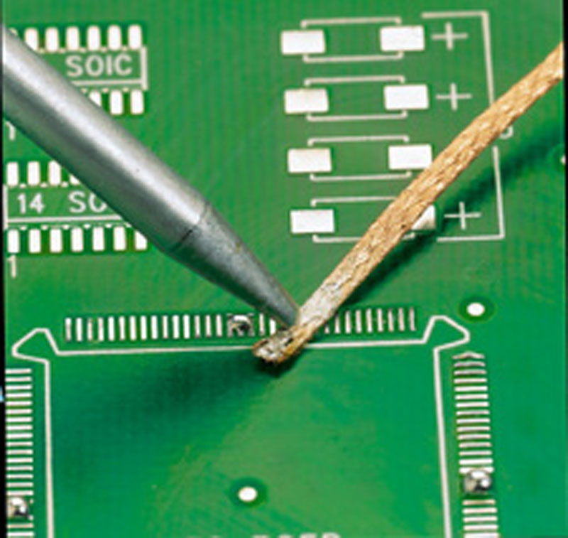
You can split this kind of
tasks in two basic methods:
de-soldering by use of
vacuum pump or similar tool
or
de-soldering by use of aids
like solder wick ( see picture at right side ...)
and a third alternate attempt to extract parts not
by removing the soldering tin but instead just
heating it
till it becomes �liquid and the pull out the part (
by use of a "hot air gun" ) .... but this does not
only demand a advanced set of tools but also very
experienced knowledge about use of heat....
( it's so delicate to use
this method because it bears the risk of damaging
the part..... )
solder wick is sold with
different widths .... |
 |
That solder wick is a kind of
braided copper material that has been dunked in a
fluid that speeds up the soldering tin to get very
liquid. After that aiding stuff got dry that wick
gats cut in lengths of 2 to 5 meter and winded in
small supply case.
When it gets heated it supports the tin to get very
liquid and sucks that soldering tin in the wick. The
process of sucking the tin results from a power
called "capillary pressure". There is one
trouble with that wick: You never know which period
of time that wick has been stored on the shelf in
the store......
and the wick looses by time it's ability to aid the
tin getting liquid....
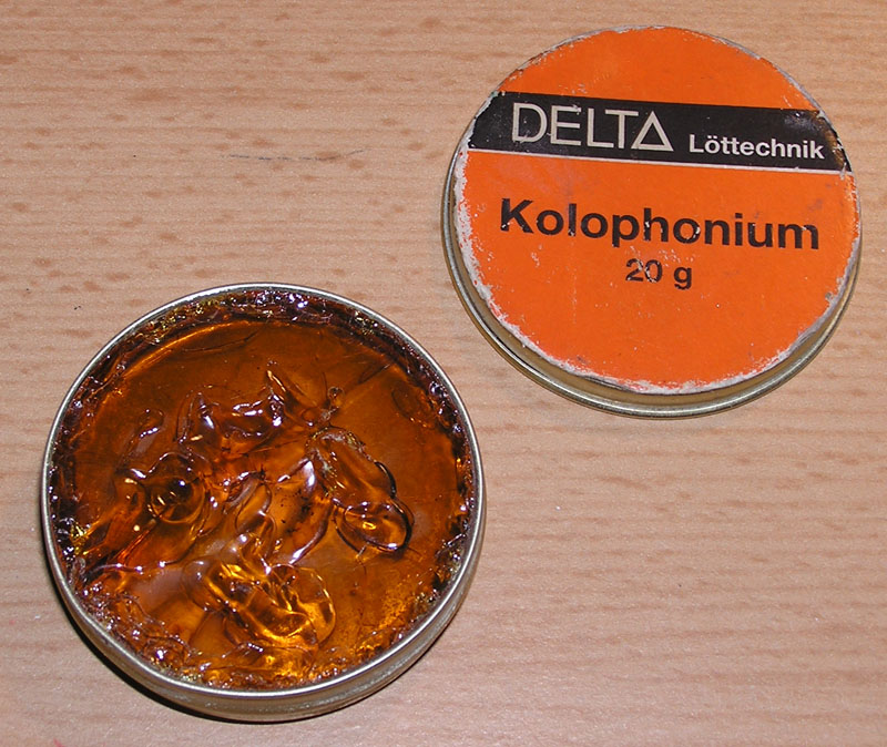
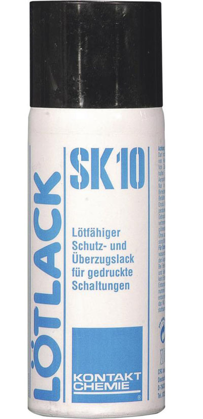
In such cases it's a good
idea to apply by yourself some Kolophonium or other
soldering aid like soldering grease to the wick. Few
pictures below there is a picture of a common used
soldering aid spray. I usually use that to add a
short spray shot of it to the wick and it then
immediately again recovers it's ability to support
the tin getting liquid and supporting the wick to
suck away the soldering tin from the cleaning area.
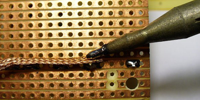
The explanation of the task
itself is rather short and simple:
Heat the soldering wick on
top of the soldering tin that is to be removed ( and
use at slightly higher temperature than usually by
soldering ) till the soldering tin gets fluid and
gets sucked by the soldering wick. When soldering
wick is full with soldering tin slowly drag the
clean soldering wick below the soldering tip towards
the "cleaning area" till the complete amount of the
soldering tin is removed.
Note: As explained above
the soldering wick is sold in different widths and
the larger the amount of soldering tin is that is to
be removed the larger width of soldering wick should
be choosen for that task.
This is a kind of task that
also is very dependent to experience - so it's a
very good idea to collect some experience at a
"exercising board" at the beginning to get
experience of requested heat and timing and the
speed that you may drag soldering wick across the
cleaning area.
And bear in mind: On long
term this is a rather expensive method of
de-soldering. The method using the vacuum pump is
cheaper and nearly same effective.... the wick
method should only be used if the vacuum method is
not handy due to the missing ability to get access
to the opposite side of the soldering joint
( for example below a component or socket ).
|
  |
|
The very moment you can access
at the component side also the soldering joint it's
the far better method
and choice to use the vacuum
pump.
There are several videos
available at youtube that display the methods and I
place here several links to that videos to see the
task in real movements:
https://www.youtube.com/watch?v=WeLgZjtK9vk
displays use of the soldering wick
https://www.youtube.com/watch?v=qJ8kTnOok7s
displays how to desolder
with a de soldering vacuum pump
and at :
https://www.youtube.com/watch?v=gQda5iibZos
you may watch the advanced
de-soldering a TQFP-IC with a hot air station
- in such cases it's sometimes recomended to
"cleanup the site" from remaining soldering tin with
soldering wick to end up with really clean area !
|
 |
another general explanation
at:
https://www.youtube.com/watch?v=UwsGnO630vY
or at:
https://www.youtube.com/watch?v=SD0Gtm5pEO4
and finally at:
https://www.youtube.com/watch?v=Z38WsZFmq8E
|
 |
    |
 |
| |
|
 |
 |
|
|
 |
| |
|