| Resurrection / Debugging of an Apple II or II+ | ||||||||||||||||||||||||||||||||||||||||||||||||||||||||||||||||||||||||||||||||||||||||||||||||||||||||||||
|
When a Apple II or II+ sytem gets released from a long term
storage itīs recommended to examine that system very
carefully to avoid damage from the involved parts and
interfacecards. Itīs srictly recommended to followup
exactly this line of procedures. One of the reasons for this procedures is to narrow down possible reasons of malfunction. That saves a lot of time and besides it also is a kind of standard routine that helps to detect most of the common problems that may occur when a system is resurrected.
The very start is to prepare the tests: Unplug all interface cards and
markup at the card with an adhesive label the slot where the
card has been unplugged from.
towards the top ( rear side ) to the letter "K" amd the notation at the very bottom row starting at the left side with the number "1"
towards the right side with the number "14". The 2 transistors of the base
oscillator "Q1" and "Q2"
are located at A1. Row 2 is located from D3 to D10 and itīs responsible for the memory from 16kB to 32 kB. Row 3 is located from E3 to E10 and itīs responsible for the memory from 32kB to 48 kB.
The rest of the memory from
32 kB to 64 kB is located at
the so called languagecard that
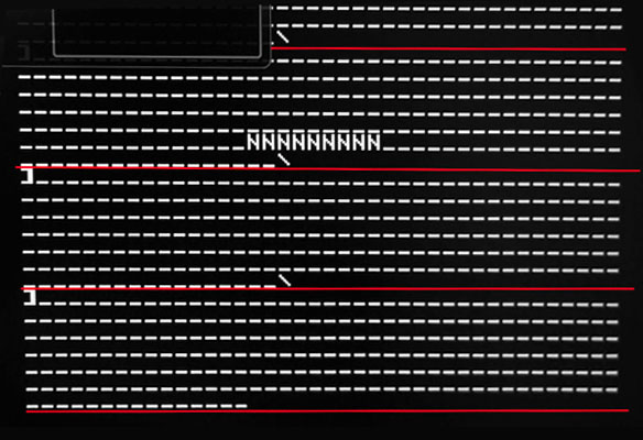
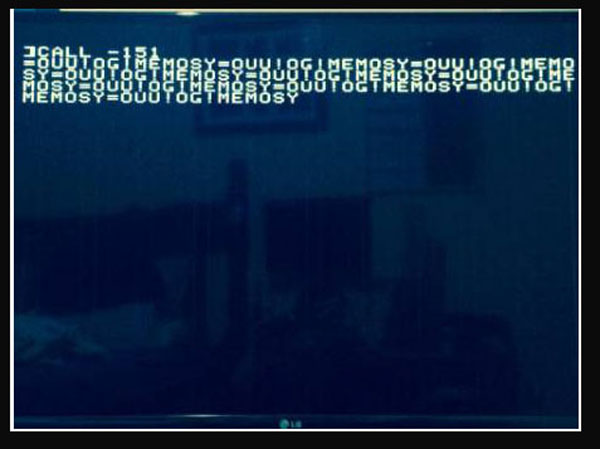
is normally inserted at slot 0. the prompt at the display: This means: a) no interfacecard inserted b) only first 16 kB of RAM inserted ( row 1 ) c) keyboard is connected to the mainboard at socket at location A7.
Be careful when uplugging the RAM chips ! They are very sensitive to static discharge and therefor they must be handled very careful. Immediatly
after unplugging a chip it should immediatly be stored at a
antistatic foam.
Before we start with the testing some additional information about the common RAM chips: Itīs very strong recommended that all RAM chips in one row are as similar as possible ( same kind, same manufacturer ) !
In general all chips have common kind of marking printed on top of the chip: XX 4116 -nn
XX =
Manufacturer
All RAM chips within one row
must be of same kind of speed !
This rule overrules the
following manufacturer rule ! at that chips counting pins is
counterclock wise. rows that way that the unmixed row is at the mainboard and the mixed one is at the language card.
"clean rows" towards front - mixed rows towards rear of the computer !
manufacturer and same speed !
So now back to the testing:
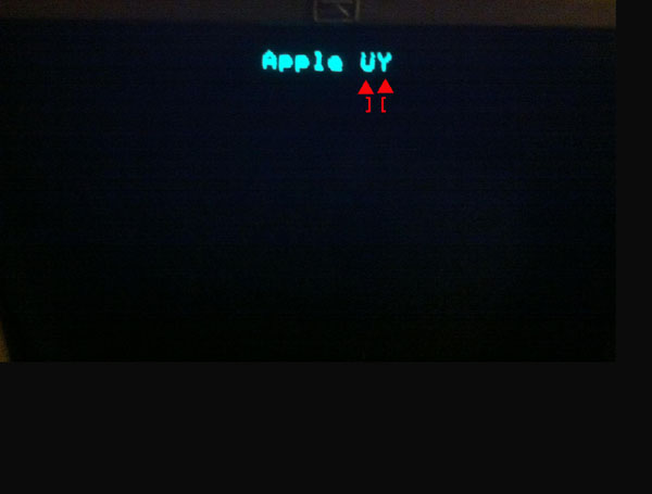
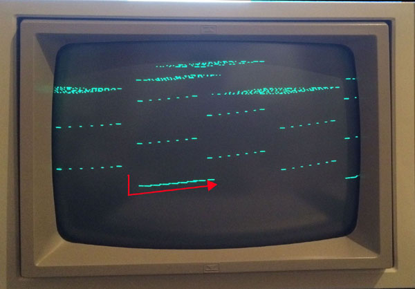
2) CPU In most cases such a mistake will result to no display at all.
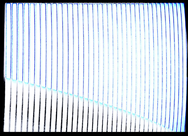
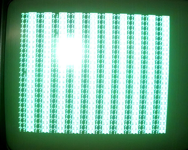
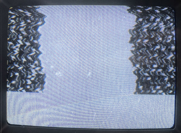
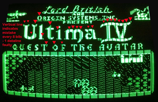
3) Adressingbus In such a case in general the display will crash and only display four or eight large vertical orientated squares or square bars.
4) Databus In such a case in general the display will crash and only display four or eight large vertical orientated squares or square bars.
5) RAM chips
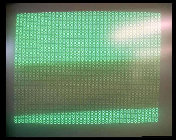
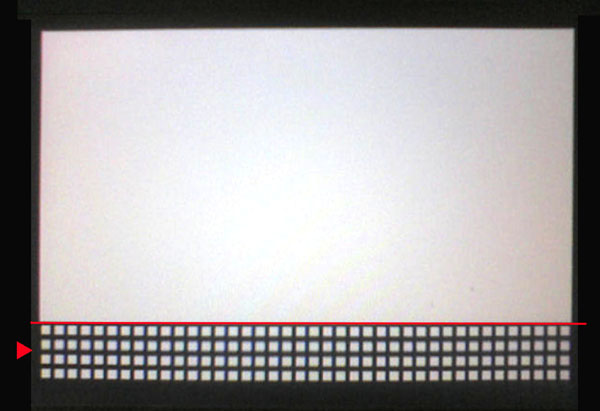
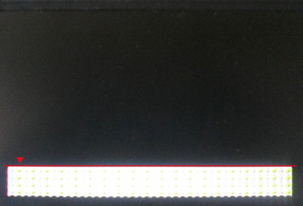
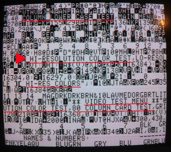
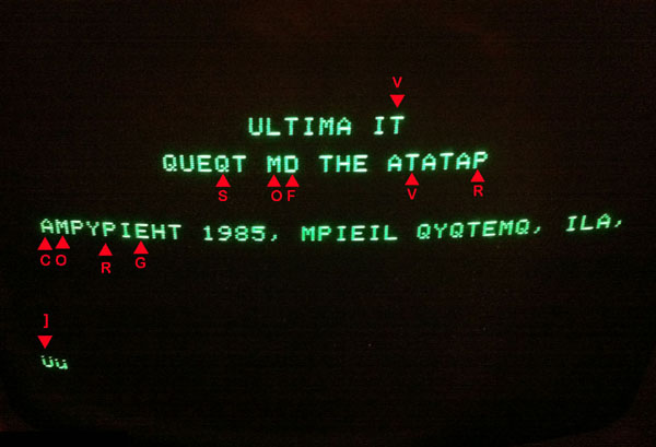
In such a case in general you will get a display of "splashing random characters".
6) ROM chips
=========================================================================
there will be different kinds of solution to narrow down the problem to a specific chip.
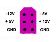
at the pin marked as Ground. The
red testing cable shall be used for measurements.
to avoid damage to the ICīs ! This
is also valid if the power supply unit itself issues unusual
noise or abnormal smell.
In a few days
i will add / update this page with a detailed description of
this specific task. in the front rows B and C and hunt for so called "spikes" that may disturb randomly the function of the computer and indicate that a capacitor is not any more within
its specified limits of ESR value.
http://www.applefritter.com/?q=content/apple-power-supply-capacitor
In case of a damaged CPU there is
only one solution: exchange of the CPU and replacement of
the damaged IC.
3)
In case of adressing port
malfunction one or more of the 3 adressing port chips
8T97 at position H3,
H4 or H5
is responsible for the trouble.
4)
In case of trouble with the databus
there are 4 sources of trouble possible: c) depending to the version of
mainboard you have at the right side from the CPU ( away
from the side heading to the power supply ) by swapping the responsible chip with a spare chip of the exactly same typ might solve the problem.
5)
In case of this kind of trouble you might swap chip by chip one RAM chip after the next chip in the row C till all chips of the row have been examined and after each swap trying
to boot up by a short power up of the system to examine if
the system solves the boot up
While
performing this task there are 3 important things to pay
attention: next set of chips as a row by the same procedure at row C till you have a complete working row of RAM chips and then repeat his procedure with the third row again in the row C and after that the row of chips from the language card. After you have a final set of 4 working rows of RAM chips you may add the second row of chips in the row D and after a power up checking correct function you may add up back the third row at E again followed by a check of power up
procedure hunting for the correct boot up display.
6)
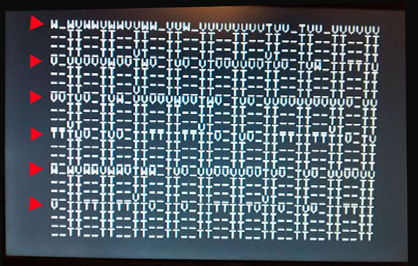
If a ROM is bad in general the
adresses displayed in the previous line before the monitor
prompt are within a similar range. 1 - the adressing itself 2 - a damaged ROM-chip. Itīs nowadays not that easy to get
a replacement ROM but at the moment there are still
replacements out there....... - but you must pay attention ! The
pinouts of the ROM and the EPROM are not same !
If the mistake is related to point 1 ( the adressing )
there are in general 2 possible sources for this kind of
trouble: and the second possible point of trouble might be a damaged 74LS08 at position H1.
run all tests including the memory tests ( also at the languagecard tests ) then the keyboard test the display test the ROM tests.
Before adding additional cards itīs also recommended to check the function and speed of the attached diskdrives. This kind of procedures is explained at this pages and itīs follow up pages.
Then you may start adding the remaining cards step by step to their slots preferrably to their default slots: sloot 0 allready occupied by languagecard or 16 kB RAM card. slot 1 =>
Printer Interface card slot 3 => 80 column card slot 4 => Z80 CPU / CPM card or alternating CPU card. slot 5 => soundcard or additional card for storage ( RAMdisk card, Controller for Harddisk IDE or SCSI or second disk controller card ) slot 6 allready occupied by diskcontroller slot 7 => special videocard or
RGB card or additional card for
RAMdisk or Harddisk interface.
( some comments will be added
in next days ! )
|
||||||||||||||||||||||||||||||||||||||||||||||||||||||||||||||||||||||||||||||||||||||||||||||||||||||||||||
|
Description of "normal" bootup behaviour:
|
||||||||||||||||||||||||||||||||||||||||||||||||||||||||||||||||||||||||||||||||||||||||||||||||||||||||||||
|
||||||||||||||||||||||||||||||||||||||||||||||||||||||||||||||||||||||||||||||||||||||||||||||||||||||||||||
|
due to european laws and german court decision: I hereby declare no responsibility to any "deep links" resulting from the links in this page. I have no influence to the pages linked hereby in this page and the contents in those pages. I therefor can not take any kind of responsibility to contents in the pages, where these links direct the readers browser to nor to the contents resulting from following up links from those pages. The reference to contents by this links is dependent ro the status of the date when the links have been set ( April 2013 ) and it might occur that references and contents may change by the fact that domains may have been discontinued from their former owners. In such cases i can nott take any kind of responsibility to the changed contents. this is specialy valid to banners, advertisements or merchandising links in the targeted pages. |

