APPLEBOX
Adaptor for Apple ][
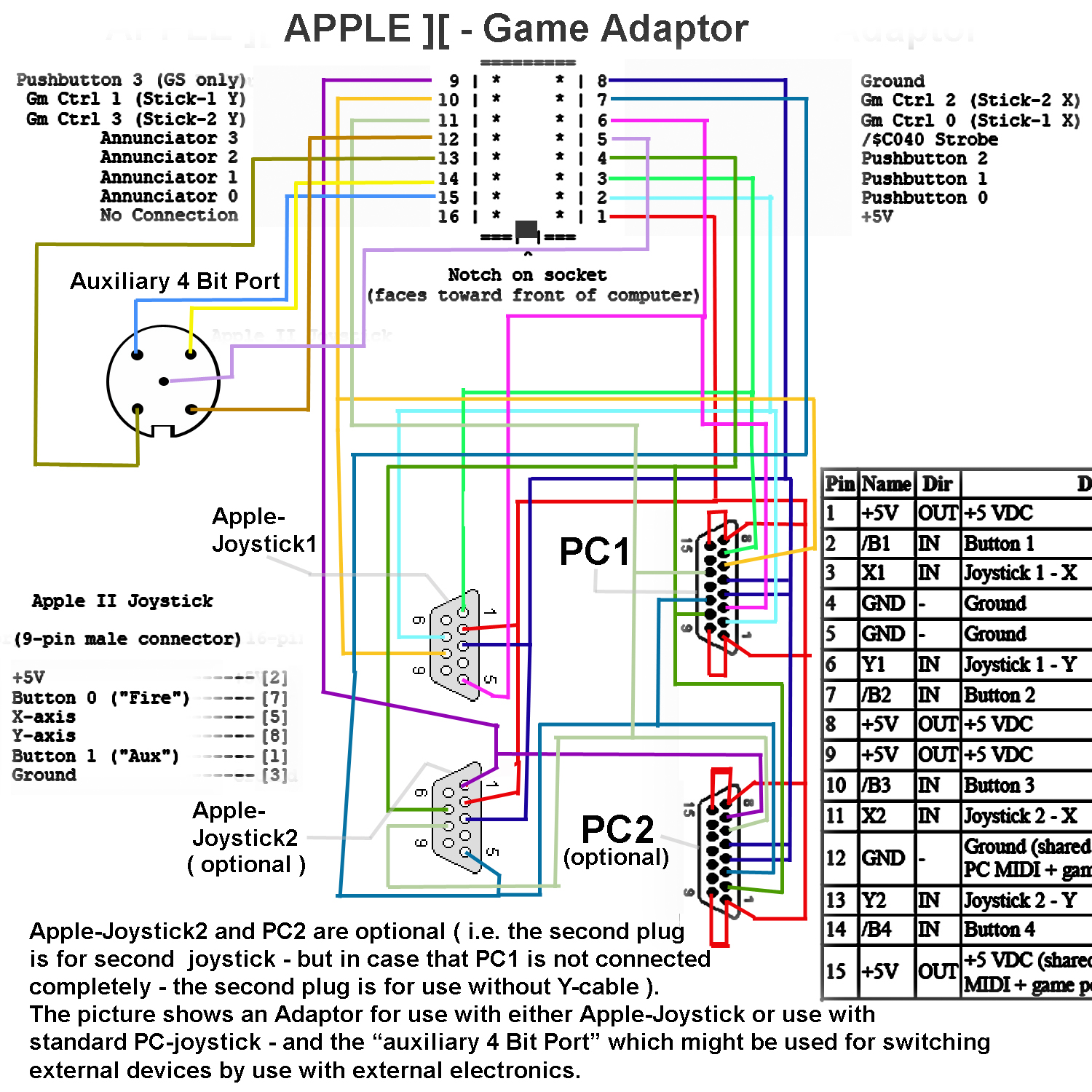
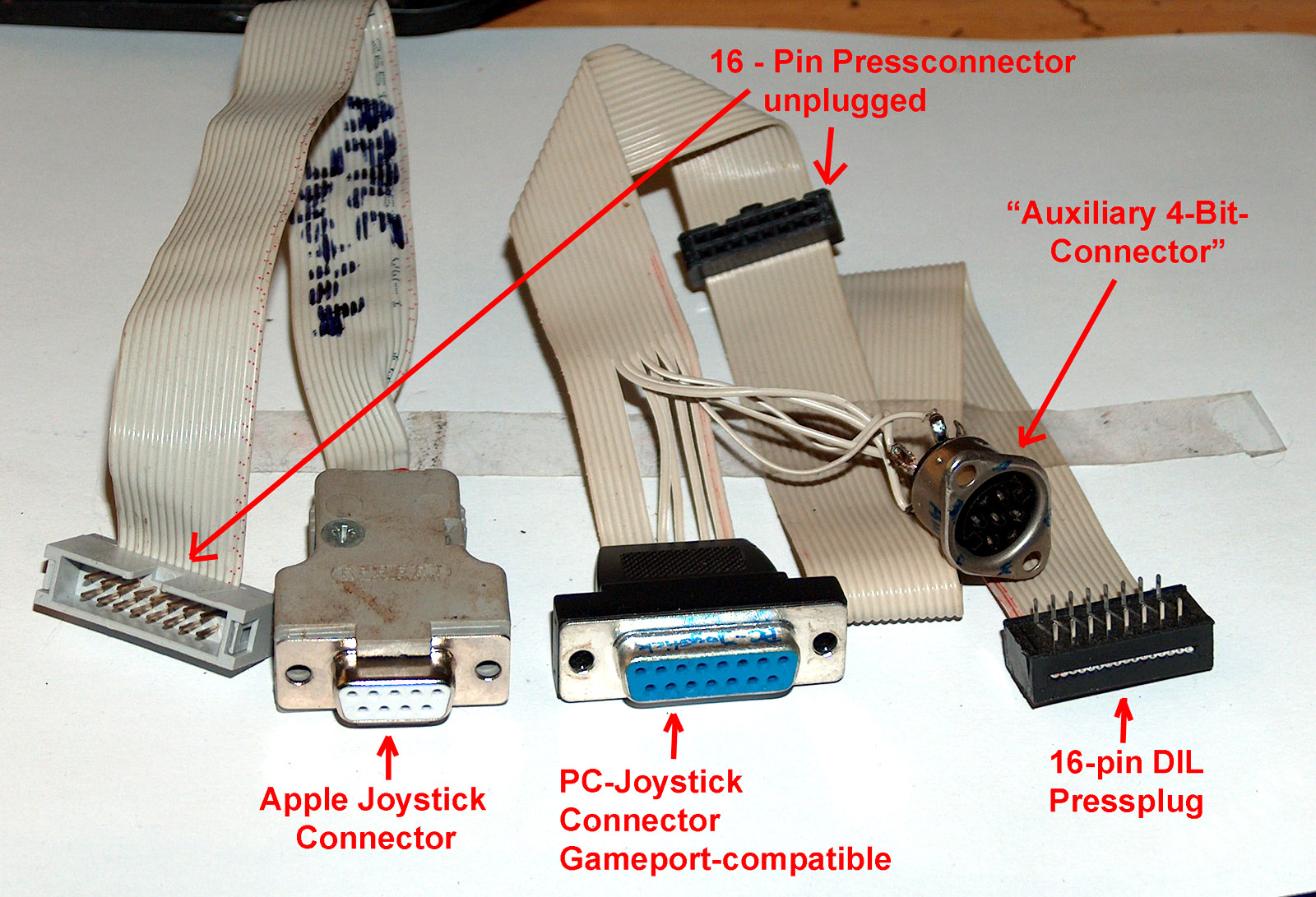
computerseries to be used with either Apple-Joystick or PC-Joystick
- and additional 4-Bit Connector to Annunciators
|
|
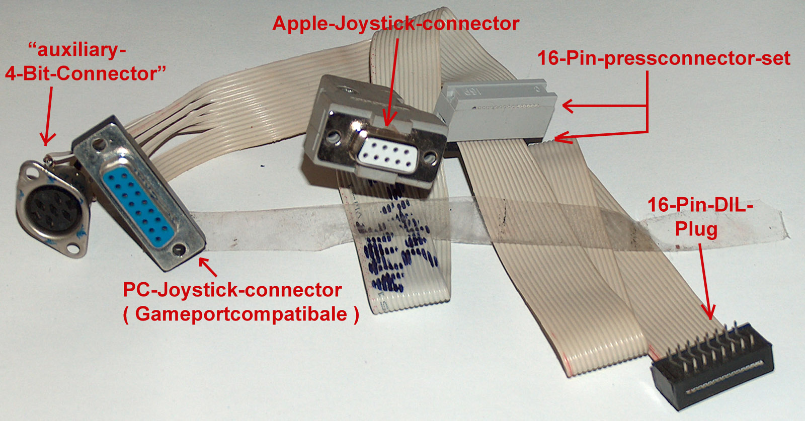
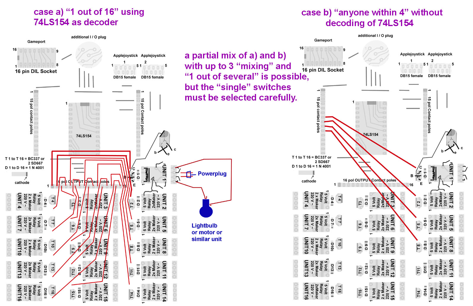
Nowadays not all Apple-fans have access to the original Apple-Joystick do it might be usefull to create an adaptor the enables these people to use instead a common PC-Joystick...... This description shows how to make such an adaptor and besides offers to create a version that permits the use of one of both kinds of joystick and besides it permits to add a further plug that gives access to the 4 annunciators of the gameport - they may be used with external electronics to switch by softwarecontrol from the computer and few external electronics external devices. Per Switch only one transistor and a relay is needed in the most simple version. You can switch up to 16 devices if you add a decoder and few additional electronic parts. This permits for example to make a burglar-alarmset by computercontrol or a lightorgan for the partyroom..... Some examples for such projects will be added within the next weeks..... in ealier schooldays such projects have been rather common to learn how to programm a system as controlsystem... so it is quite good idea to add that connector to the adaptor....
|
|
||||||
 |
||||||||
Note: In the picture below each line is desplayed in one single color - allthough different colors may cross eachother the connections only exist within one single colorshade - never connect any of the different colorshades together ! |
||||||||
 |
||||||||
 |
||||||||
|
First Update : 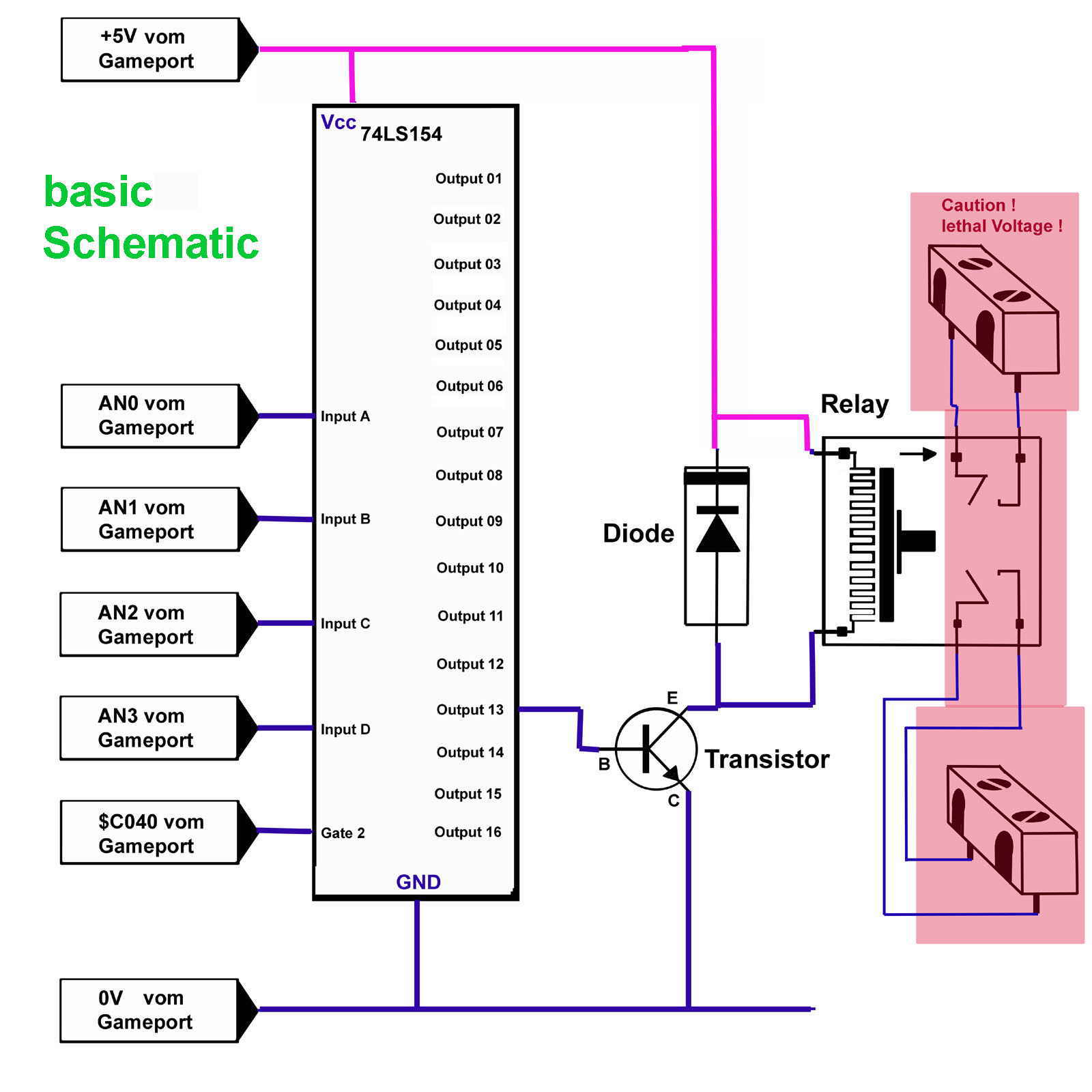 |
||||||||
|
here i introduce the PCB that might be used for the experiments and programms that will be introduced in the update No.4 the purpose is to start allready with the creation of the PCB that will be used in the further updates ! The PCB contains: 1 x 16 pol DIP Socket 2 x DB 9 Plug female 1 x DIN 5 pol Plugconnector 1 x 24 pol DIP Socket 1 x 74LS154 16 x Transistor BC337 NPN midpower 625 mW 50 V or SD 667 16 x 1 N 4001 SI Diode 50 Volt 16 x 5 Volt Relay ( 2 x Maker / Closing switch 110 Volt USA / 220 Volt Europe ) as low as possible needed power to activate ( 150 mA if possible ! - but not more than 250 mA ! ) [ otherwise a external powersupply must be used and the 5 Volt powerlines from computer must become truncated ! ] 16 x 4 pol screwed connection block 2 x 15 pol. pinstrip 1 x 16 pol. pinstrip
PCB-board 160 mm
x 100 mm |
||||||||
|
Here the placementplan as PDF-file |
||||||||
|
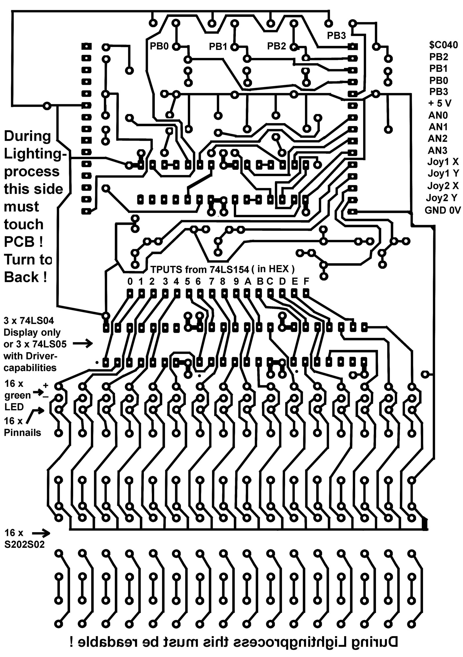
while making the PCB with Photoprocess please keep attention to text marks to keep sure that during the lightingprocess the film is correctly positioned ( see text at the bottom ! ) 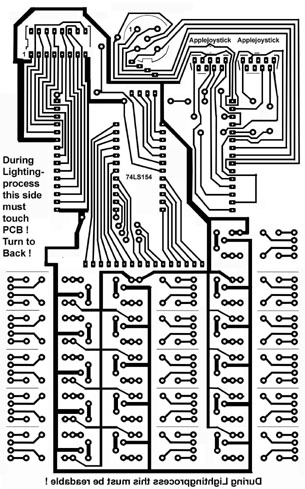 For correct sized Film download it as PDF by the link of the image below and print it according to the Text within the PDF-page ! |
||||||||
 |
||||||||
 |
||||||||
 |
||||||||
 |
||||||||
 download this code as PDF.file |
||||||||
 |
||||||||
|
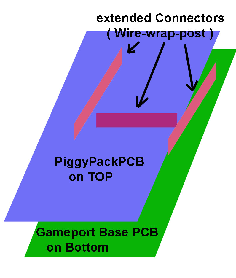
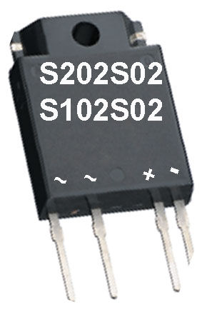
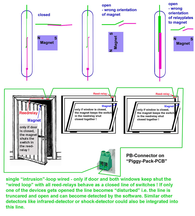
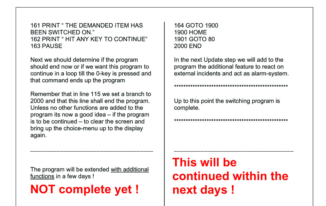
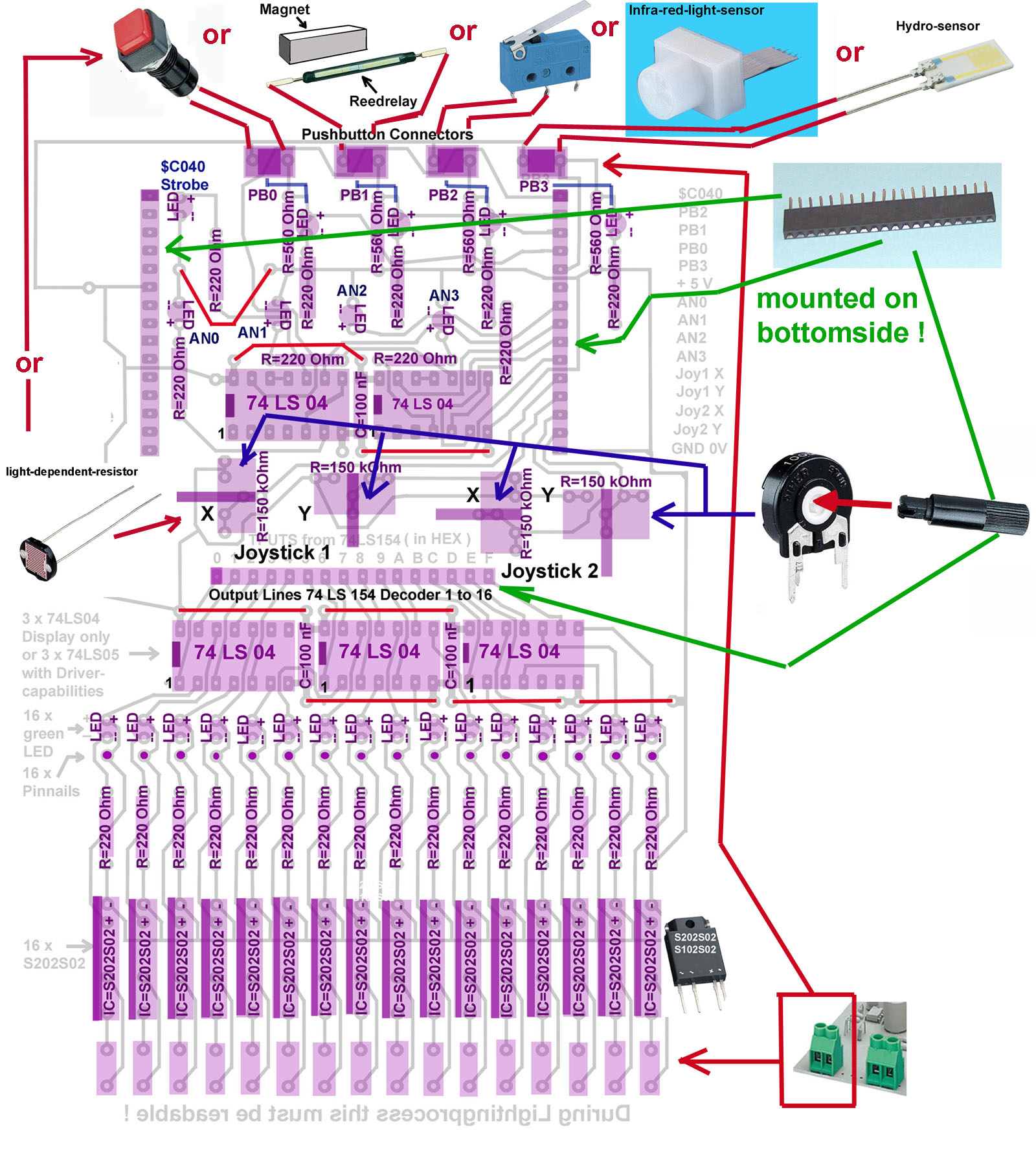
Here comes the next large Update with the introduction of the "Piggy-Pack-PCB" it´s designed to be pluged on the top of the Base PCB introduced above. It´s first purpose is to display the state of the switches with LEDS so the status of the softswitsches AN0 to AN3 and the Pushbuttons PB0 to PB 3 are indicated by red LEDs that turn on, if the line is "High" and it also shows by LED which line of the 16 outputs from the 74LS154 is turned on by switching to "LOW". The other part of the extension provides the user with the possibility to connect different devices to the Pushbuttonlines and it gives access to the variable resistors of an "open joystick" as well as the ability, that the 74LS154 may be interfaced with so called "Solid State Relays"instead of normal Relays on the Base PCB. Solid Stae Relays do not use that much power from the powersource and are more simple in use ( but indeed they are more expensive ! ) With this expansion we will proceed with new coding and we will solve some experiments with devices like Reed Relays, which are used in home-security-systems to keep doors and windows under survilience. We will also do some experiments with the variable resistors to learn something about positioning coontrol which is used in devices like robotic-controls.
So lets start at the
moment with the "Piggy-Pack-PCB": |
||||||||
 |
||||||||
|
and here is the PCB-film itself: |
||||||||
 |
||||||||
|
and here are the links - to the placementplan and here is the link to the two datasheets for the "Solid State Relays" |
||||||||
|
the "Piggy-Pack-PCB" schall be pluged on top of the Base PCB like this:
and here is a
sample for an very simple intrusion-warning-system : |
||||||||
 |
||||||||
 |
||||||||
 |
||||||||
 |
||||||||
 |
||||||||
 |
||||||||
| to be continued with the next days ! | ||||||||