the APPLEBOX


          the Expansion Box from Mountain Computer
   a legendary expansion to the Apple ][ series

      reverse engineered and de-mystified


       Copyright note: The pictures used in this page, have been taken from members gsmcten, macnoyd* and Keatah ( all members at the Applefritter Forum )
                              * the pictures from macnoyd, result from the ebay offer he successfully won
                                 Therefor the copyrights of the pictures displayed at this page remain of course to the members at AF whom the units belong.
                                 The other pictures here resulting from the reengineering process remain with their copyright to me and none of the contents from this
                                 page may be used ( not even partially ) in any other webpage without the permission of the copyright owners.


The story that leaded to the creation of this pages started months ago, when a member at AF ( =Applefritter ) anounced that he won a offer at ebay
and thereby purchased a Expansion Box from Mountain Computer, with all adds like manual, interfacecard and the external powersupply brick.
The fact that this box has been only sold in small number of units in the beginning of the 80īs - had  caused in the meantime a lot of rumors about
that box and only few information has been published in the internet.

So within that thread a couple of members decided to make a complete documentation about the box. We decided to create a kind of "brain-power-
task-force" to solve this task.... - when the box arrived at the member and i viewed the manual, we recognized that some important information about
the box and the interface card have been missing, like the circuitplan of both parts. After short dispute in the thread we decided to carry out the task
of a complete reverse engineering of the unit. This process has been also covered in a related thread at AF, that contains in the meantime more than
300 postings (!), but this also might cause difficulties - if specific information is to be researched for repair of such unit. This turns out to become more
valid the longer that thread gets, because a lot of pictures have been published that resulted to updates and corrections....

So thatīs why i end up here with this pages... they shall compact the informations and limit pictures to the final results - and provide an owner of such
a unit here with easy searchable information upon the unit, itīs repair or maintenance.

Starting on the task for the documentation i first recieved a huge bunch of pictures from the member gsmcten, who purchased that box from ebay.
Later when it turned out, that we would need much more information about the "hidden" traces beneath sockets and ICīs to become able to perform
a reverse engineering. This was the very point where Keatah joined our group and he provided me with unbelievable amout of awesome pictures,
uncovering that "hidden" traces. After collecting all the data still several lines had not been uncovered / completed to final status. At this point Keatah
spent quite a lot time to measure that traces with a multimeter. Finally all data had been collected and i started to make films from the existing pictures.
Based to that film i could reverse engineer the circuitplans from both : the box and the interface card.

I must mention here that without that awesome support from Keatah, the task to uncover the circuitplans  could not have been performed and without
the other pictures from gsmcten this documentation would also be partially incomplete.  So therfor i express here my very thanks to this both members.
Some other pictures used here have origin from macnoyd, another member at AF who won another offer at ebay, not to forget that without the platform
at Applefritter.com, it would have been nearly impossible to perform that task...because all of us, that joined together for the task of reverse engineering,
got linked together by that platform, which is nowadays one of the largest active communities for Apple related stuff.


  Lets start here with a general collection of pictures,
that offer a general overview of the box and the interface card
.
 
 starting here with the views to the closed expansion box:
 
 
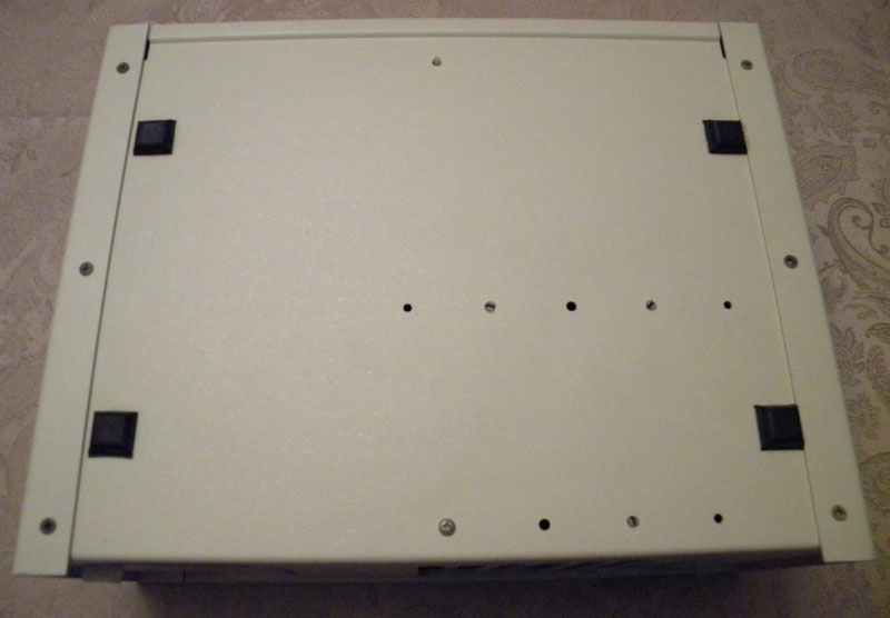
 view to the bottom of the closed chassis:

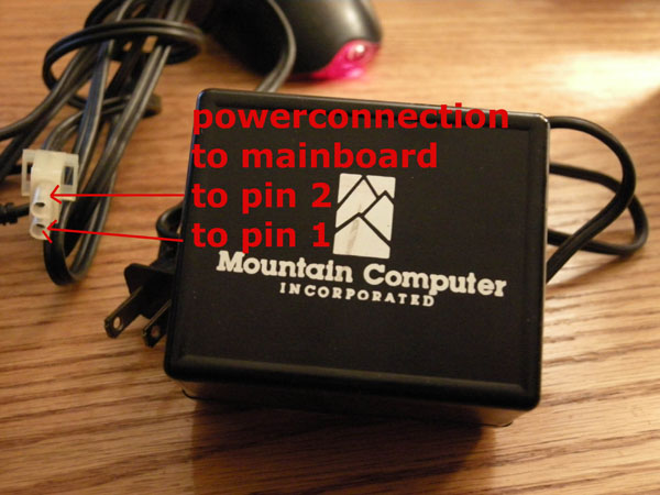
the external powersupply of the box:
 
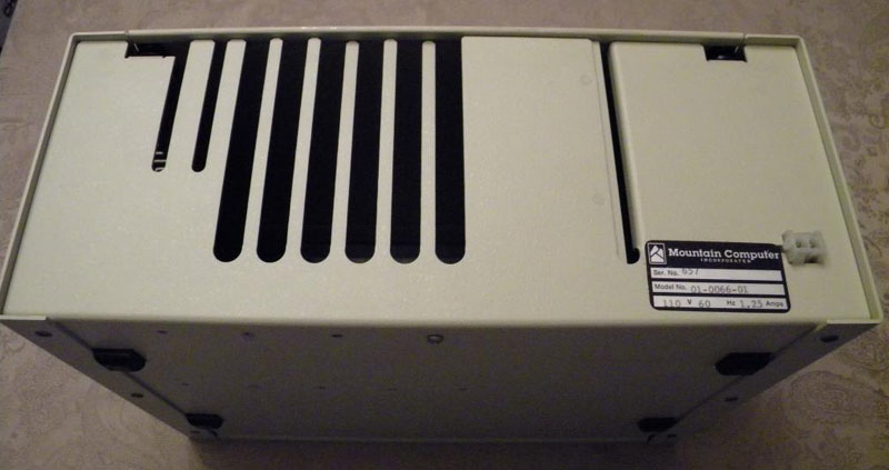
  here now the view to the rear of the closed chassis:

  the group of open slots at the left side
  might be used for cables from or to the
  inserted interface cards.

  the single slot at the right is used during
  operation of the box by the 50-pin
  flatribboncable that connects the
  interfacecard with the expansion box.

  the plastic plug connector is determined to
  plug in the external powersupply-brick
  that provides the box and the inserted
  interface cards with the required voltage.

  ( see the picture above that displays
    that "powerbrick" - it delivers 26 Volt
    AC at strength of 1,5 Ampere )

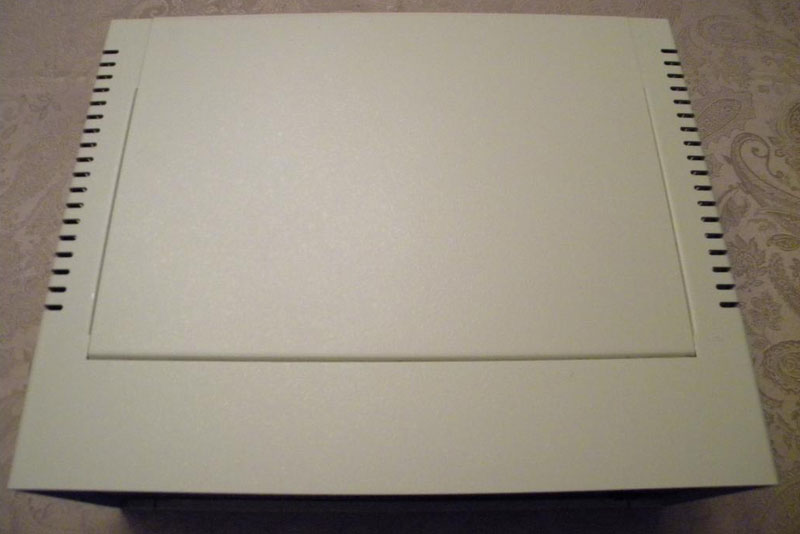
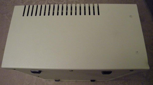
 and here is the view to the closed top of the box:

view to the left side of the closed chassis:

 
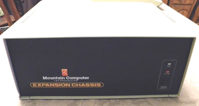
 and now here the view to the front of the closed chassis with the "info"-LEDs and the selection-switch:


  So now after we have viewed the closed box,
  letīs lift the top and view inside.


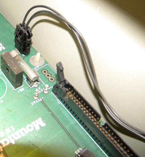
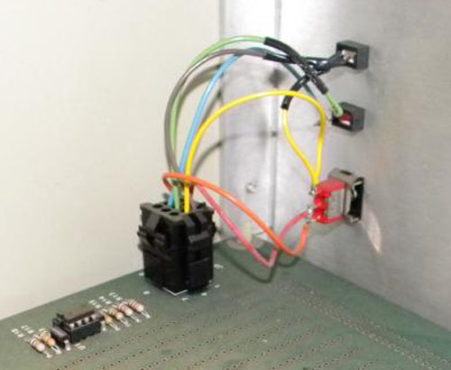
 at this side there is inside a
 cablefrom rearconnector for
 the powerbrick to the
 Mainboard:


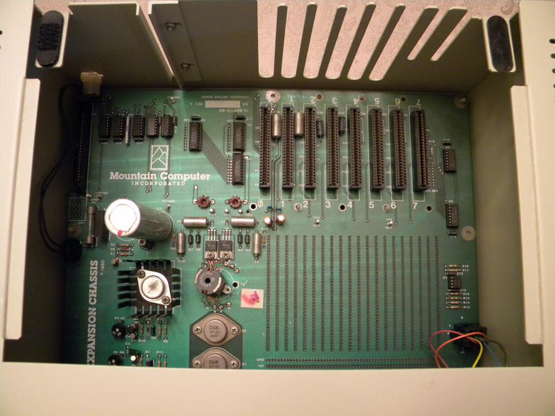
    here is a view inside the box taken from the front with view to the rear:


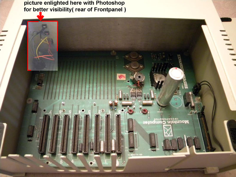
  here is the view inside the box from the rear to the front. The part that leads to the LEDīs at the frontpanel is
  enlighted with Photoshop. From this part, a picture has been taken for details and is displayed right side of this
  picture. This picture was taken from a box damaged by transportation - one of the "big-caps" has broken off
  rightsided from the remaining one left in the box - the remaining electrolytic capacitor is the large silver
  cylinder in the middle-right of the mainboard. You can see the marking on the mainboard for the missing
  broken component. So itīs normal with working boxes to see 2 (!) "big-caps". in other pictures you will see both
  "big-caps" but in the other picures both have blue coating..... another damage from transportation was the
  release of the "switching-coil" which will be explained later in detail.


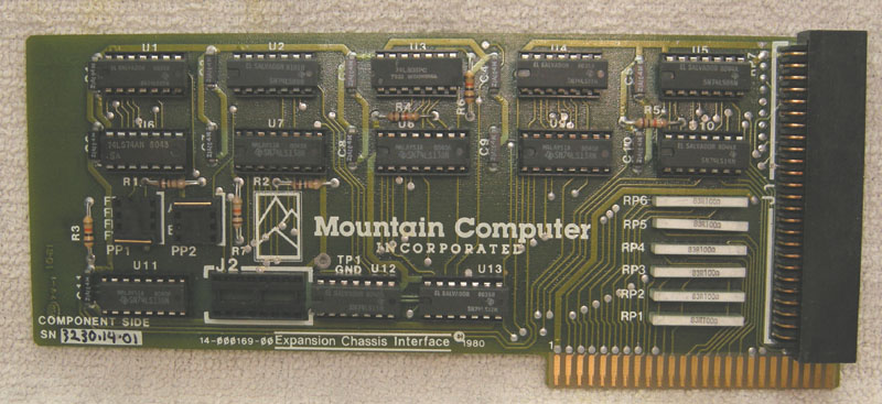
   And now we will view the interface card that is used
  to connect the box with the Apple ][ series computers:


   here is the view to the interfacecard from the componentside:


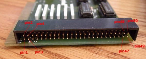
  here is a view to details of the 50-pin connector:


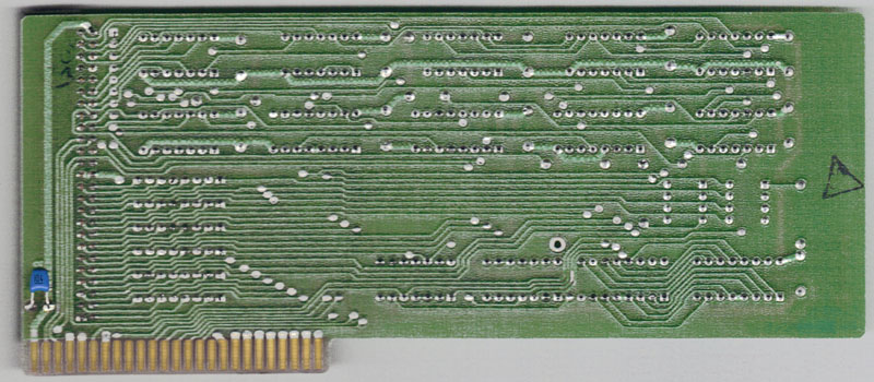
   and here is the view of the interfacecards from the solderingside:


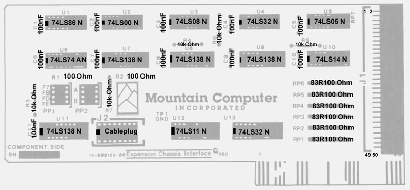
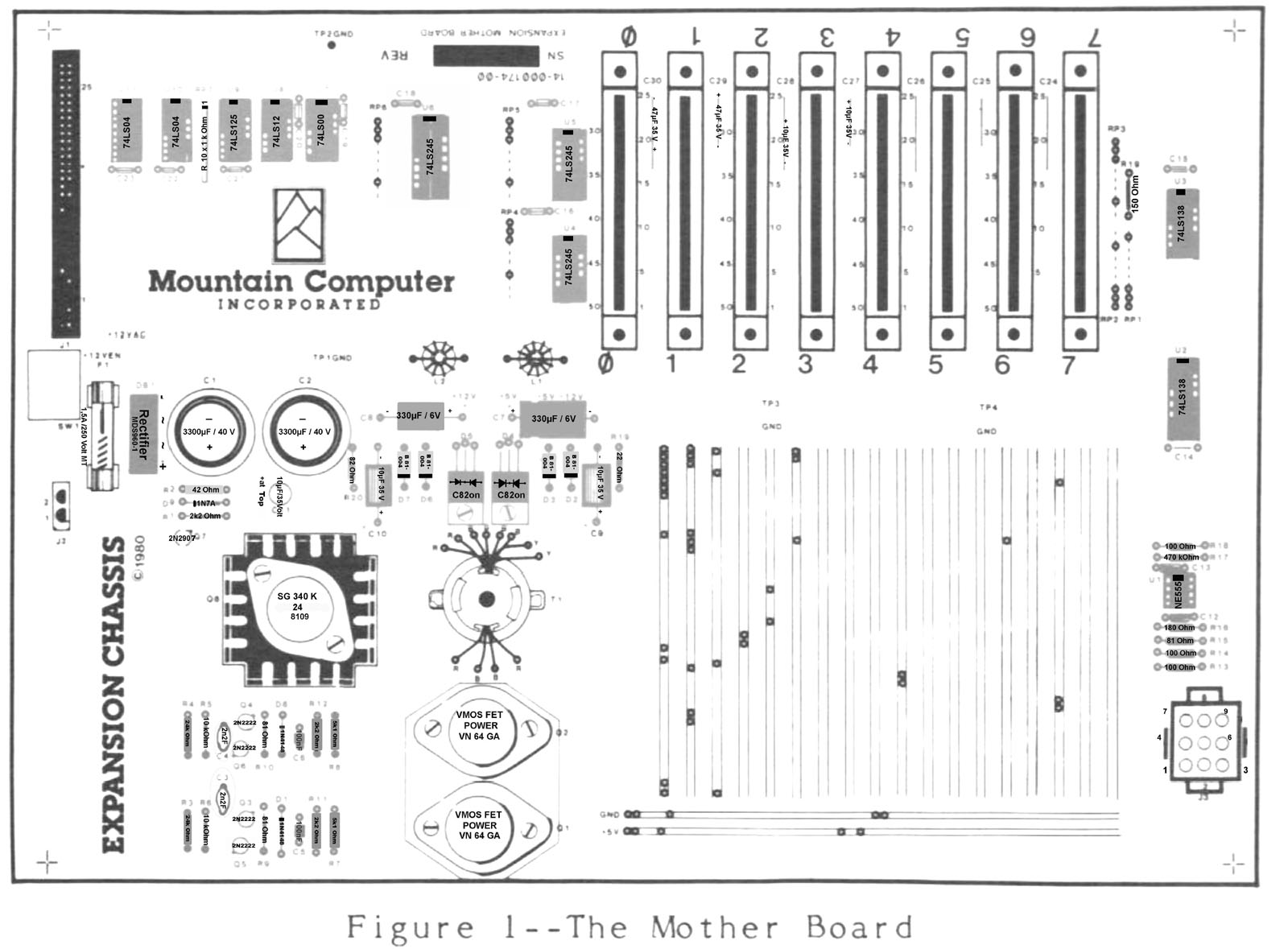
 Here is a short view to the front of the manual, and the 2 pages that display by drawing the interfacecard and the mainboard in the manual....
 In fact there is one difference to the original pictures in the manual:
 I have added in both pictures the names / values of the components within that pictures.


the frontcover of the manual:


 and here the drawing of the interface card:


  and here is the drawing of the mainboard:


   here is the link to the next page - where the story is continued =>


  <= here is the links to turn back to the indexpage of the Applebox