 |
APPLEBOX |
|
|
For those, who want to design own Interfacecards ( reagrdless if they are aiming to connect a external device to the computer or make a card for special use like Audiocard or Measurementcard ) it´s a rather good idea to read the mentioned book. It explains which laws rule the design of Apple II Interfacecards and how to access the cards from Software. The included experiments target to demonstrate how the adresses on the interfacecard are hardwired and how to use that hardwired adresses from within the program as input or output ports and the different techniques how to code and access that ports. Unfortunatly the book only contains the description of a kind of Prototyping board that shall be used between the Apple II and the breadboard, but lacks about the layout of such connection - it only has splitted parts of circuitplans of such protoboard. Therefor the following description might be quite usefull to those, who intend to perform the experiments described in the book and don´t want to start up from the scratch and collect the sircuitplans, join them together and make that prototypeboard to create the connection between the breadboardsystem and the Apple II. This board contains the chips and the layout how to monitor the the interface and the coded logic on the breadboard and therby verify the own design by experiments. Targeting to save resources the Interface for the Apple II and the prototyping card are linked together as one large board and after making that board the user may saw the interfacecard apart and link both boards with a flatribbon cable. this permits the interface card to stay inside of the Apple II , while the prototyping board and the breadboardsystem remain outside apart of the Apple II. |
||||||||
Here is the general view of the prototyping card and the interfacecard after they have been sawed apart and connected together with a flatribbon cable. Please note that the prototyping card has a section on board that is designed to supply the card and the breadboardsystem with independant stabilized power from external transformator with 24 Volt and 12 Volt ( both brancehes each 1 Ampere ). The only requirement is that the GND od the Apple II and the external systems are linked together to ensure that the systems interact with the correct voltage levels. This is assured by the connection of the interfacecards. In case that the external powersupply is used the wires connecting the power from the Apple to the prototypingboard should be not soldered in place. 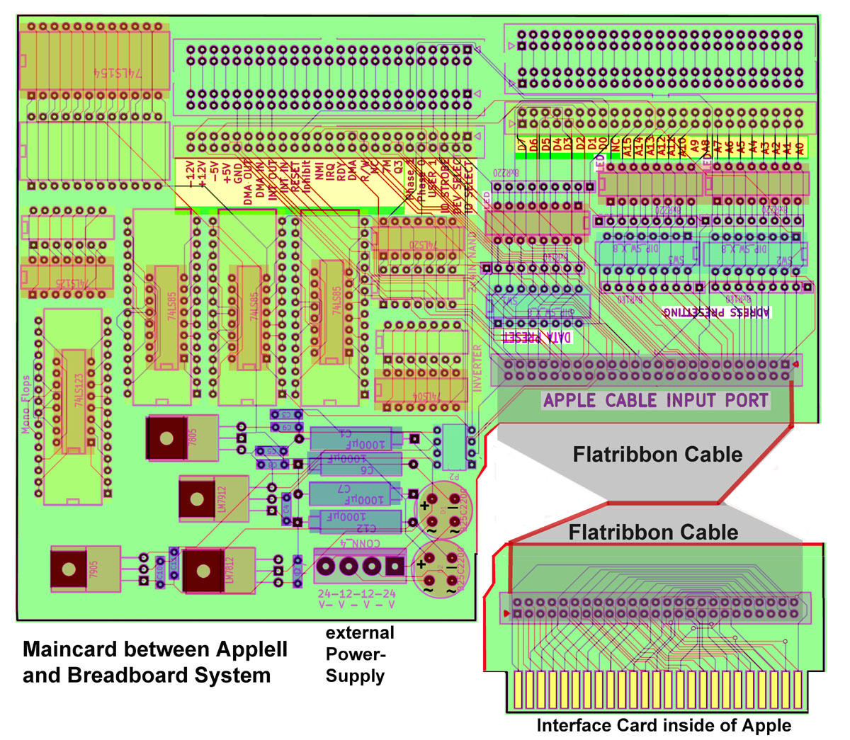 Please also pay attention to the red side of the ribboncable indicating the side of pin 1 ! |
||||||||
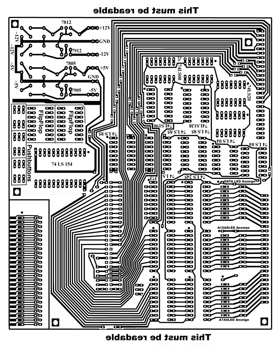
here is the view to the solderside of the card: 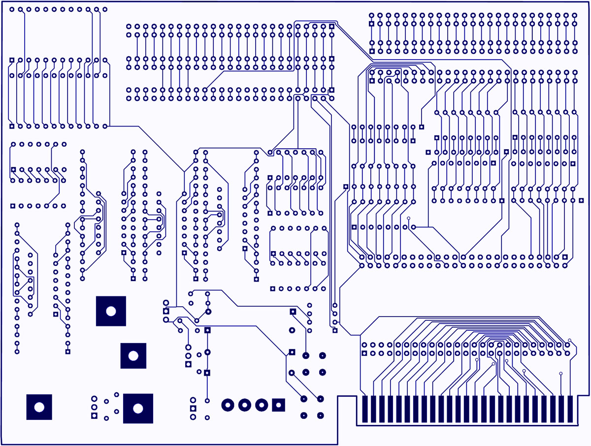 |
||||||||
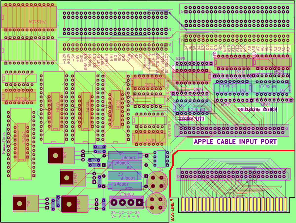
Here is the view to the traces at the componentside: 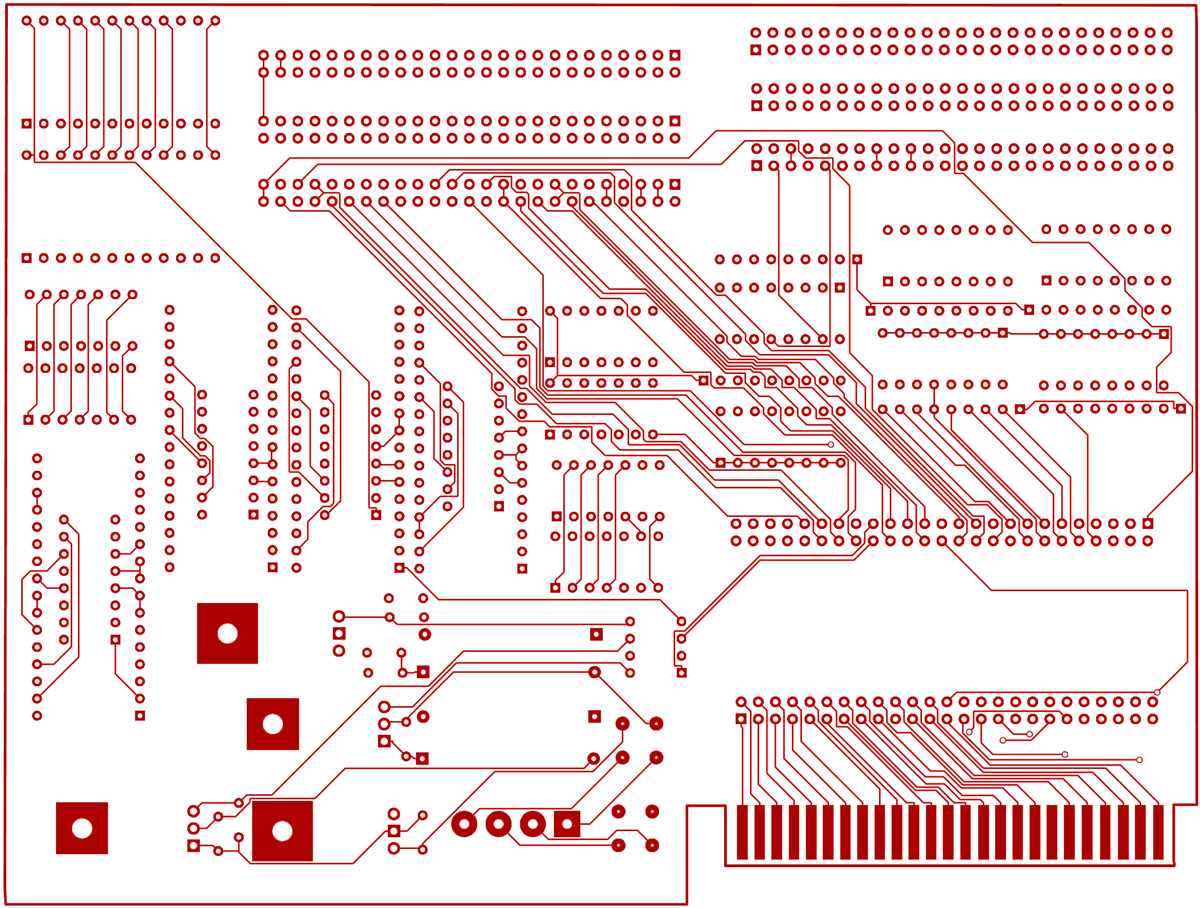 |
||||||||
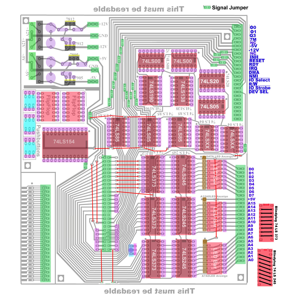
And here is the view to both layers combined together: 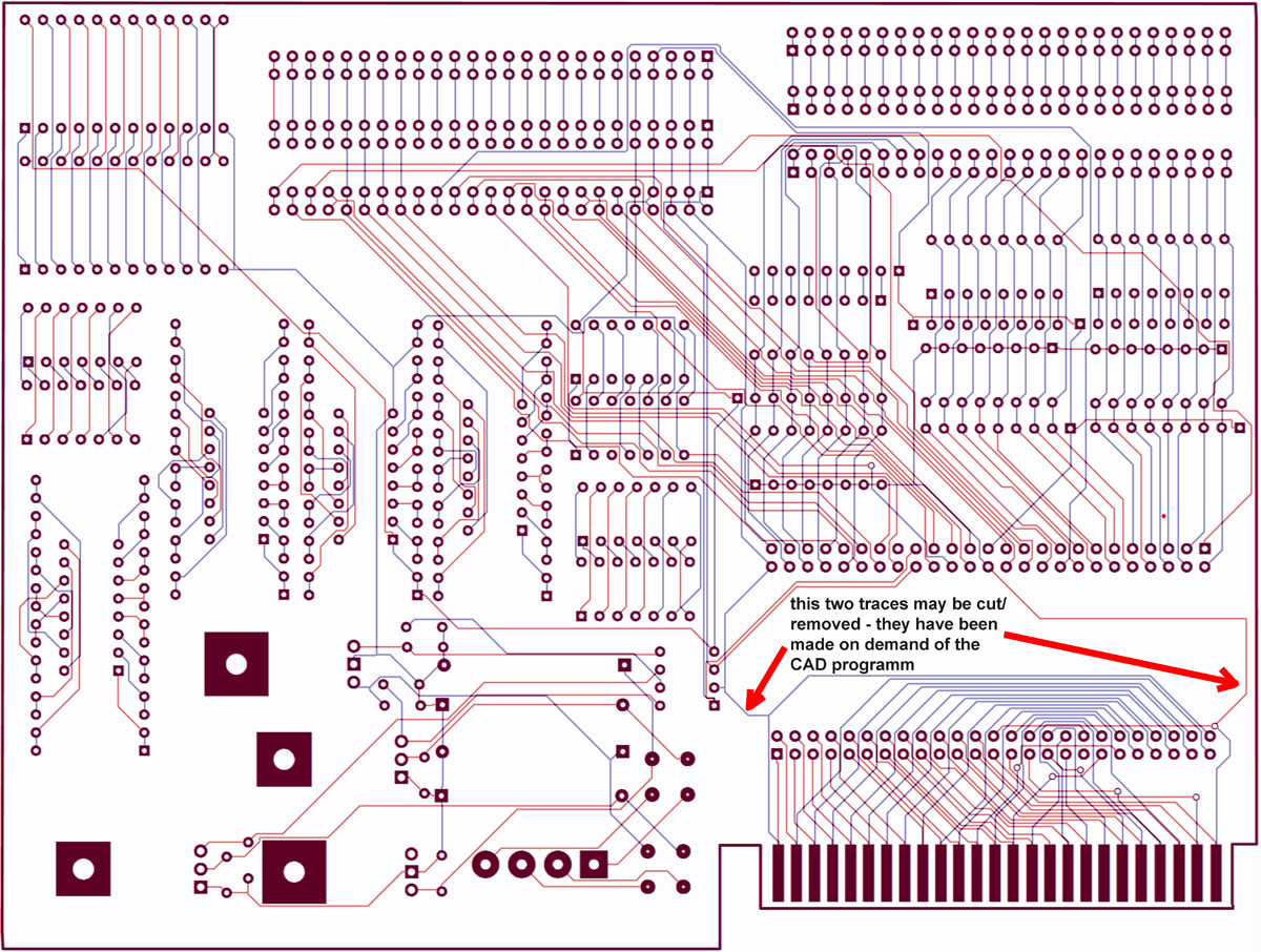 |
||||||||
and here is the view to the layout of the components: 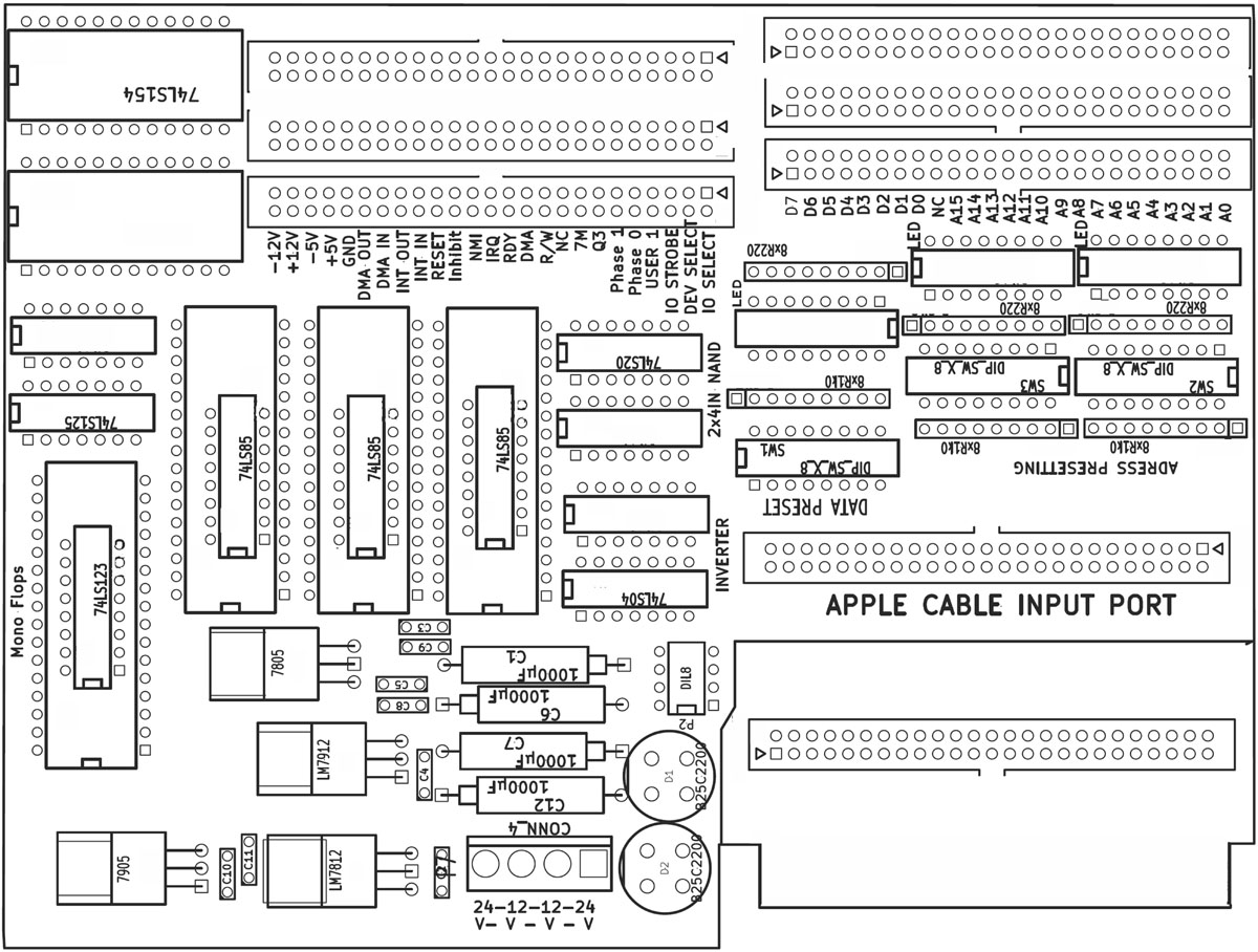 Please note that several chips have been placed inside of larger IC-sockets. The purpose is the each pin of the chip has connection to 2 pins of the larger socket and therefor there are for each pin of the chip 2 pins availiable for access at the surrounding socket for use with the breadboardsystem. Those chips which are proposed for use only by one connection the related socket to grant access to the pins is located besides of the chip and grants only one pin access to the related gate. |
||||||||
This is explained by the colored fields of the following picture:
|
||||||||
For use of this board it´s highly recommended to download the related book by using the link in the title of this page and read the book before starting up with the experiments. Otherwise you might damage your computer ! The basics explained in the book are essential for understanding the experiments and preventing the system from harming the computer ! |
||||||||
and of course here a view to the circuitplan: 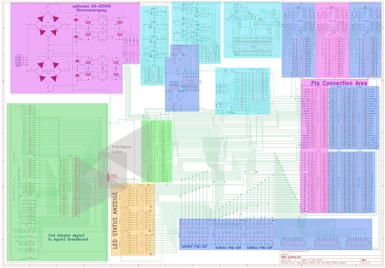 |
||||||||
Alternatively i also publish here the "older" version i made about 25 years ago.... in those days i etched my own single sided PCB´s at home with a "home brew" etching system by lighting the PCB´s with ultraviolett lightbulb and afterwards etching in a cavern made of acryl and heated with a heater usually used in aquariums and transferring air bubbles in the cavern / tank with a pump used for adding air in the water of an aquarium. The film for the single sided PCB :
The population of the PCB looked
like this :
|