|
||||||||||||||||||||||||||||||
|
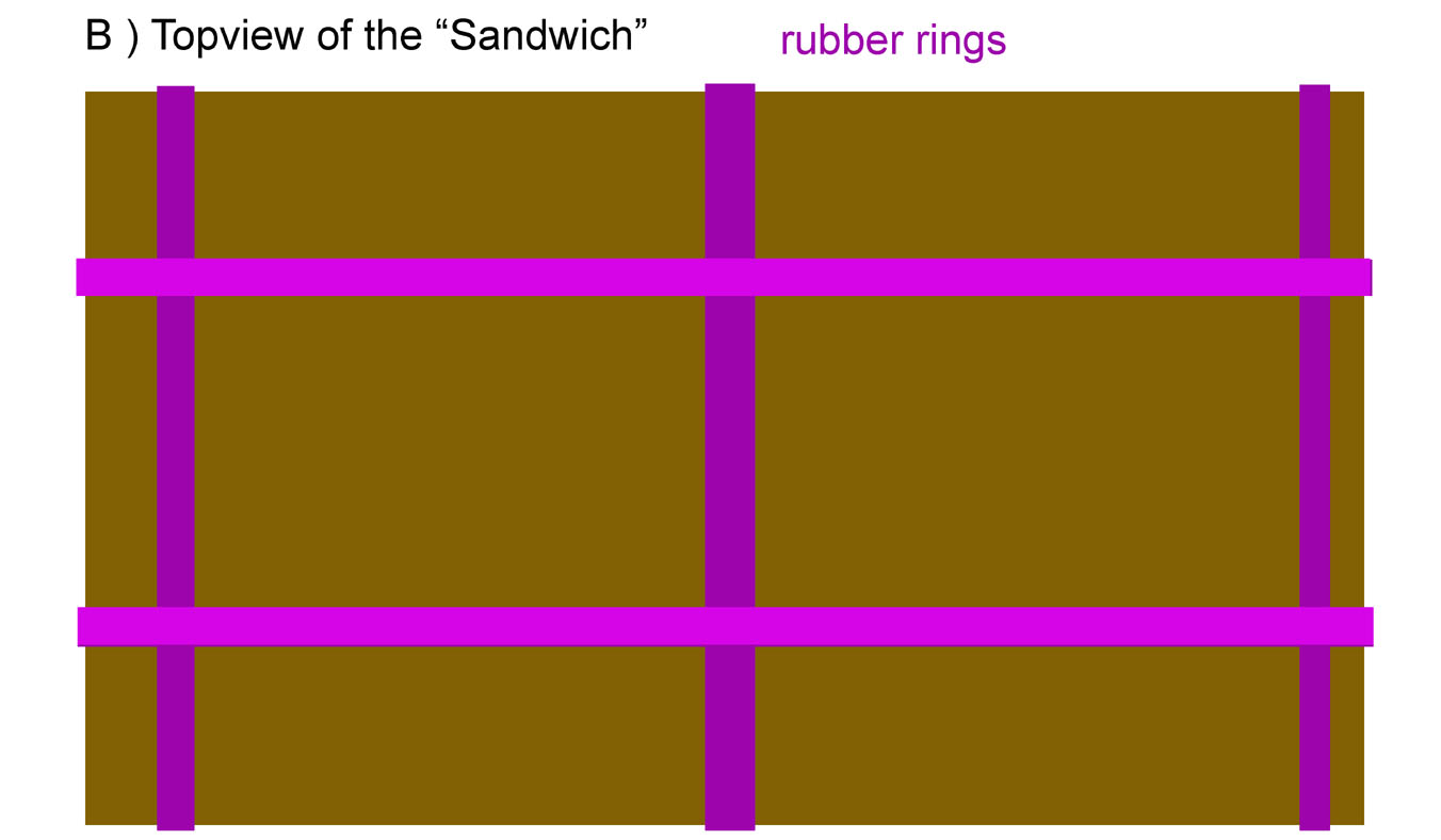
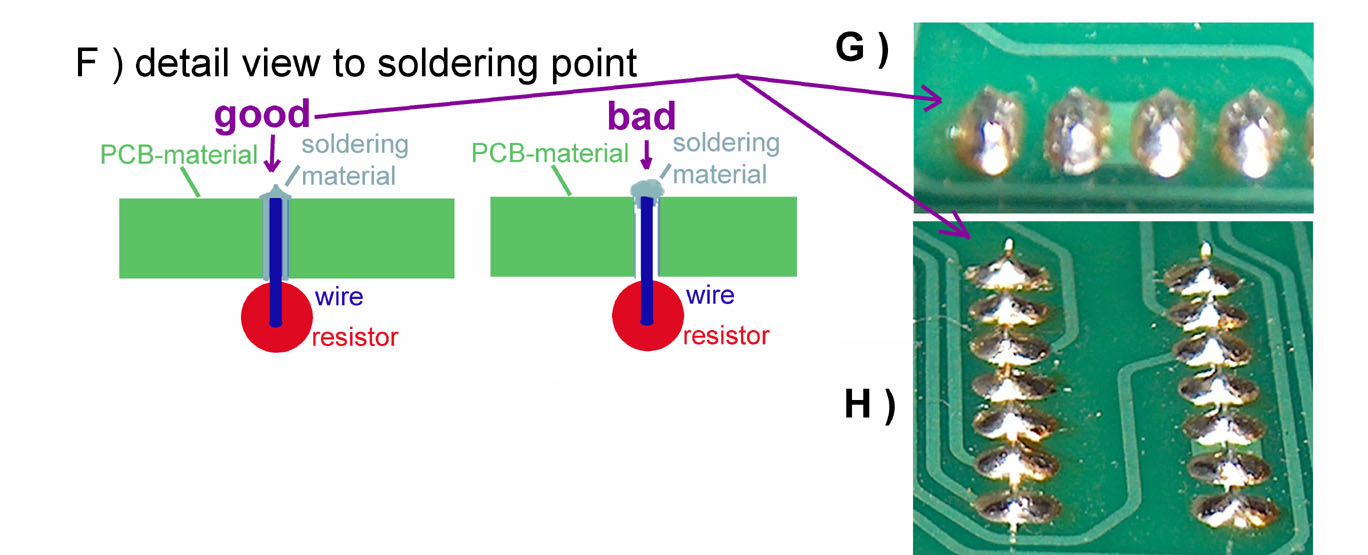
Soldering a mainboard can become a frustrating and horrible task if some tips are not performed and the results might even leed up to a nonfunctional mainboard. If the mainboard is not assembled in a professional factory with wavesoldering bath then there are several problems to handle in the most important one is that you would need a few hands more than you can offer. But there is a simple solution : working with the "Sandwich" - method. the assembly is split to several different stages - depending to the "hight" of the components.... in general a Mimeo boards for example will be split to the following groups / steps: 1) resistors 2) sockets 3) filter capacitors and ceramic capacitors 4) small electrolytic capacitors and crystal 5) edgeconnector 6) transistors 7 ) voltage ICīs and connectors 8) finally the big electrolytic capacitors and the volatgeregulator with the cooling sink First of all you will need to get a peice of stabile plywood with about 4 mm or 5 mm thickness and the size should be only little bit larger than the Mimeo mainboard itself ( there should be a border of 1 cm more at each side of the mainboard ). That board should be very stiff ! You should not be able to bend it ! This plywood board should then be covered completely at one side with a rather hard ( only little flexibel ) foam that is not to weak against heat ( no styrofoam !) by fixing it to the wood with sheets of doubleside- adhesive tape. In the first step all resistors are inserted in the board and then the plywood board is placed on the top above the resistors and then that plywood board is fixed with large and strong rubber rings like shown in the drawing below. |
||||||||||||||||||||||||||||||
When the "Sandwich" is complete and
the rubber rings are strong enough, then you can flip that
entire "package" around and start to solder the resistors.
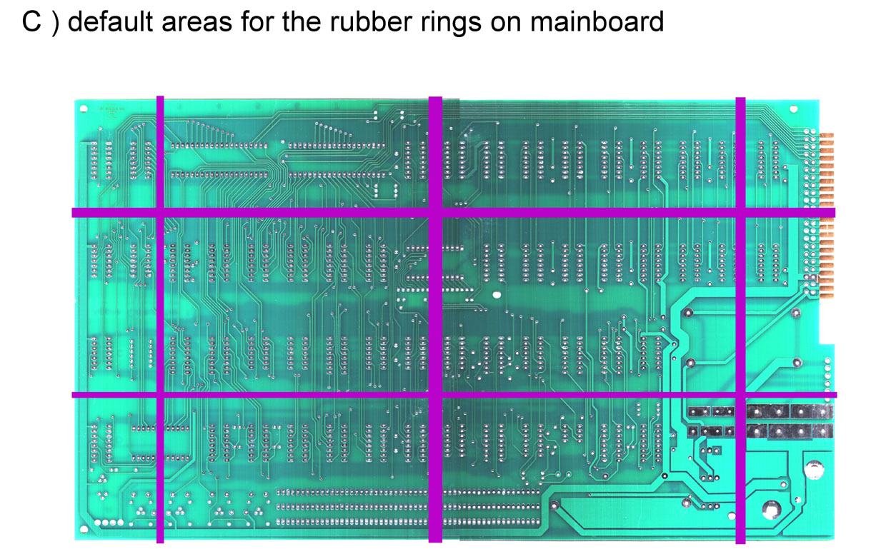
The rubber rings should be positioned
like displayed in the picture above to make sure that the
pressure of the rings is supplied equaly to the entire surface
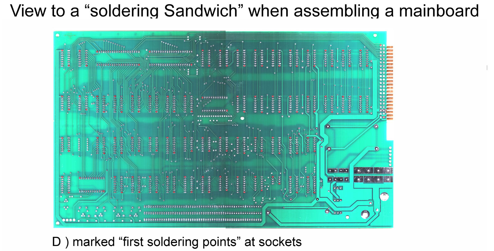
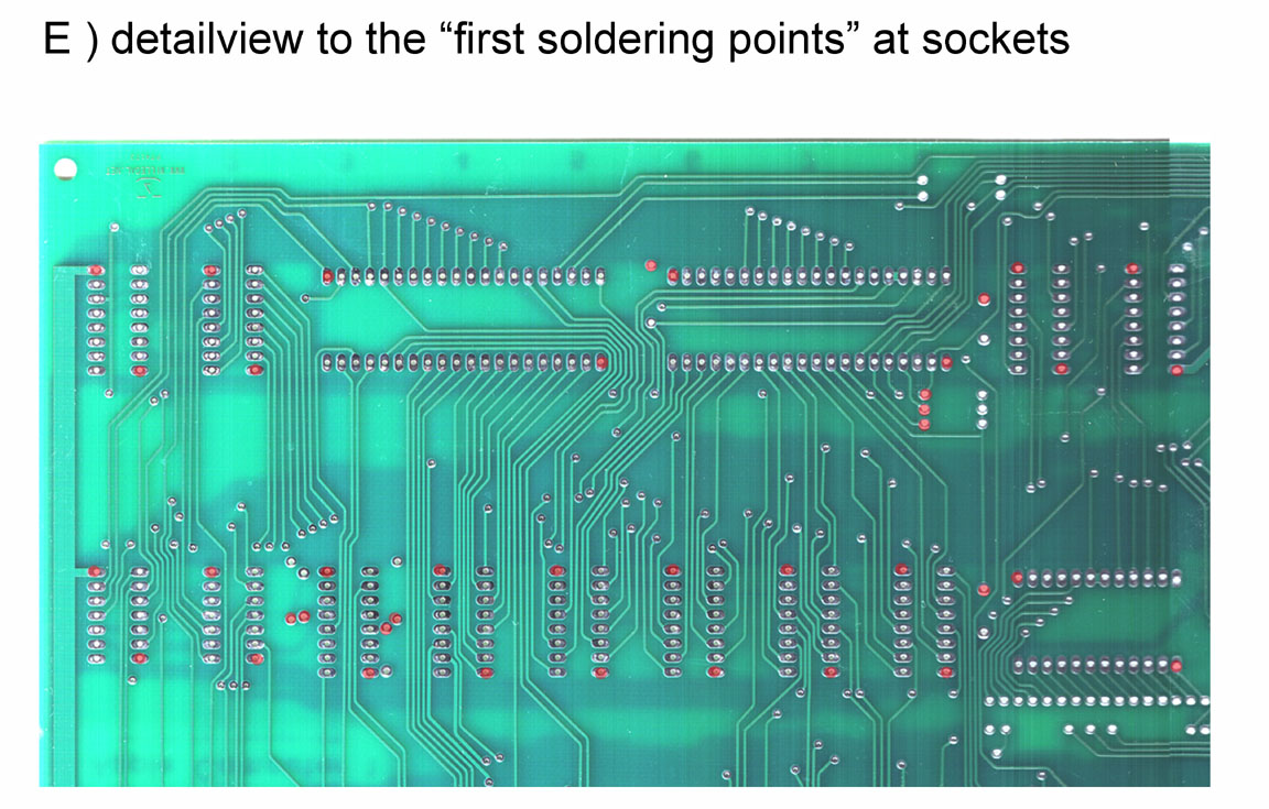
After all sockets have been fixed at 2
points you may remove the rubber rings and the plywoodboard.
Then you should heat again the soldering joints
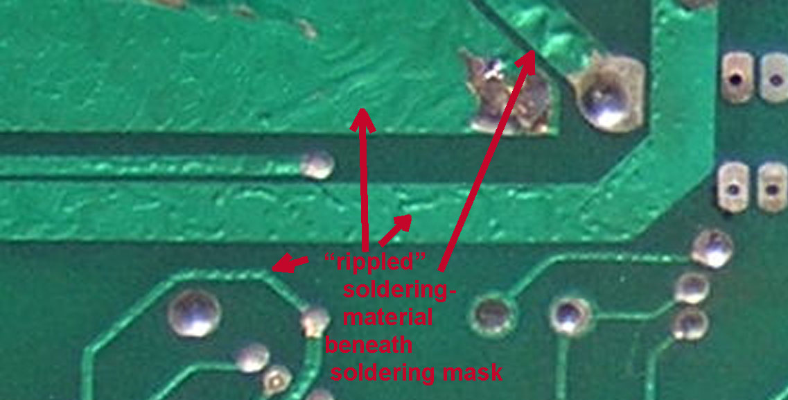
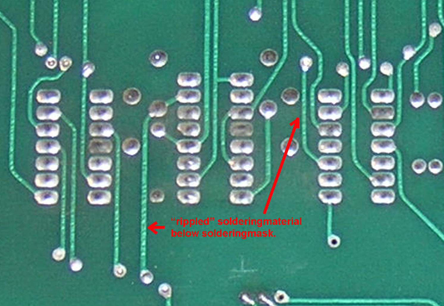
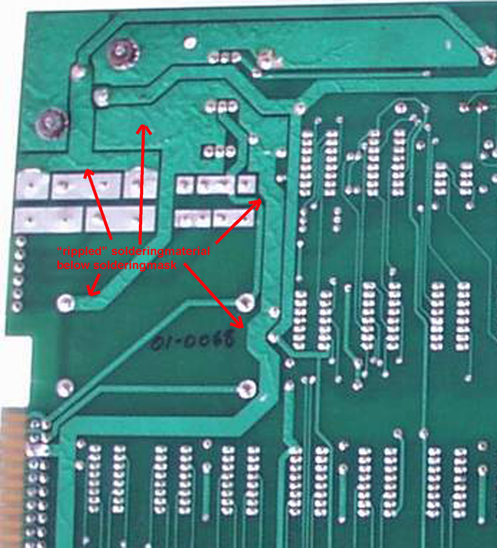
At Applefritter the member
PhilPower mentioned correctly that nobody will be able to
reproduce perfectly the solderingside of an Apple 1 and this
is the best statement to be
|
||||||||||||||||||||||||||||||
|
due to european laws
and german court decision: I hereby declare no responsibility to any "deep links" resulting from the links in this page. I have no influence to the pages linked hereby in this page and the contents in those pages. I therefor canīt take any kind of responsibility to contents in the pages, where these links direct the readers browser to nor to the contents resulting from following up links from those pages. The reference to contents by this links is dependent ro the status of the date when the links have been set ( April 2013 ) and it might occur that references and contents may change by the fact that domains may have been discontinued from their former owners. In such cases i canīt take any kind of responsibility to the changed contents. this is specialy valid to banners, advertisements or merchandising links in the targeted pages.
|

